| * For the
basics of caps see electrical theory 1.
This page is not the theory but more real
application information
such as types of caps , markings etc.
From electricians point of view the most famous is the single phase motor
starting capacitor, after that it is power factor correction capacitor then
it goes vague after that. Therefore lets start with the application first
then we do the types and so forth.
| Applications: |
Function |
Notes |
| Motor starting |
The capacitor creates a phase displacement between two
winding in order to achieve rotation. |
In order too get an armature (rotor) to rotate we need a
force to pull the armature in order to start turning so induction
can take place. Since a capacitor causes a phase displacement between
the voltage and the current for an AC supply, it does the job perfectly.
Soon as the armature rotates the motor is happy and we can cut this
additional winding + capacitor out of the circuit. Now lets share a
bit ofd criticalnformation here to prevent any blow ups:
- The capacitor is measured in micro-Farads. Each motor design
requires it exact amount of capacitance to do the starting...so it is
best to replace with equal. I don't say another value might not
work...for we all know what happens in the workshop...what I am saying
by design we come to an exact value and is is best to stick with this
value.
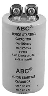
- Motor starting capacitors are high voltage for a reason and that
400/450V volts rating is there to accommodate the peak values in the
AC supply.
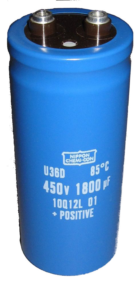
- And this brings us to the last point: A motor starting caps
is a electrolytic type cap but the "normal electrolytic caps are
polarised meaning it cannot be used in AC supply. They look the same
and sometimes even have the same voltage rating but if it has the
+(positive) and the ---(neg) on the casing - that's a animal for a
different job. Don't even try to use them -these caps explode with a bang and it
flies all over the show.
There my say is said, hopefully it helps.
See if you can spot the difference:
---
 |
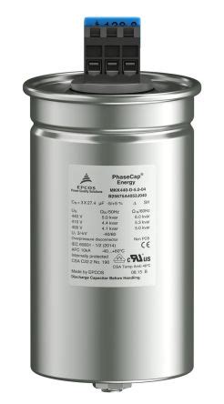
| Power factor correction |
The effect of inductance on a AC supplied circuit is to
create a phase displacement between the voltage and the current. By how
much the current will then lag the voltage is a function of how much
inductance is in the circuit. The effect of capacitance in AC
supplied circuit is that the voltage lags the current by as much
capacitance is in the circuit.
This is the direct opposite to the effects of inductance.
This means we can use one to cancel the other...and this is
exactly what power factor correction is all about, bringing that voltage
and current back in phase because if they are not we don't have
efficient power usage.
But be careful because if they are exactly / totally equal a
phenomenon called resonance happens and then things become very
unpredictable.
Then we have to add reactors (chokes - yes more inductance!) but they
are said to be detuned.
|
 |
| |
|
|
--- Capacitor values and
markings:
| Unit |
|
|
|
| Farad |
1F |
10Exp-0 |
1 Farad |
| Micro- Farad |
1uF |
10exp-6 |
0.000001 Farad |
| Nano – Farad |
1nF |
10Exp-9 |
0.000000001 Farad |
| Pico – Farad |
1pF |
10exp-12 |
0.000000000001 Farad |
| |
|
|
|
--- Similar to resistors -
in electronics capacitors also have markings where each colour signifies a
specific piece of information: In reality, for capacitors the colour
markings is not so easy as with resistors...you get the funniest ways
manufacturers can mark the caps. What I do is make sure I mark them when I
receive them...that way there is no crisis. My rhyme to remember the
colours goes like this: Black BROY Gave BeV a Grey Whip
| Value |
Value |
Multiplier |
Tolerance band is the last band. |
| 0 |
Black |
black |
Not used |
| 1 |
B... |
brown |
1 |
| 2 |
R... |
Red |
2 |
| 3 |
O... |
Orange |
0.05 |
| 4 |
Y.... |
yellow |
0.02 |
| 5 |
Gave |
green |
0.5 |
| 6 |
Be... |
Blue |
0.25 |
| 7 |
V...a |
Voilet |
0.1 |
| 8 |
Grey |
Grey |
0.01 |
| 9 |
Whip |
White |
not
used |
| |
|
|
Silver= 10% |
| |
|
|
Gold=5% (most common) |
| |
|
|
No
colour=20% |
- See if you can figure how the code work from this clue: 1000 Ohms
Colours: Brown Black Red
Now back to work:
|