|


| |
-------------==============--------------
This section is very much a work in progress -
Read it conjunction post regarding installation
| SANS |
|
|
| Mains switch can be combined 3p circuit breaker
or
3phase supplying single phase loads can be 3pole isolator and three
single pole circuit breakers (prefferred) |
|
|
| Tee joints accessible & neutral must still be a continuous |
|
|
| 6.1.5 A maximum of three conductors may be connected to any
one terminal provided that the terminal has the correct rating. |
|
|
| |
|
|
| |
|
|
-------------=============-------------
Conductor sizing
| SANS |
|
|
| Neutral same as phases unless 3rd harmonic and
imbalances |
|
|
|
Cable rating factors
Rated current size 6.2(a) to 6.9(a)
Correction factor for ambient temperature not 30DegC – Table 6.10
|
|
|
|
Calc a cable size
Buried factors:
Soil temperature Not 25DegC correction factors Table 6.11
IF UNDERGROUND: Soil thermal resistivity NOT 1.2K.m/W oil correction
factors Table 6.12 -degrees Kelvin-meter per watt
This is interesting -its here but there is
no way one can determine the correct values; I would have thought there is a
chart somewhere to use around geopraphical areas...but there is noting. and
the worst factor is 0.64...it will calculate to nearly double cable size.
Question: What to do if some cable
in roof and half in ground? I guess worst case applies. The regs does
not say.
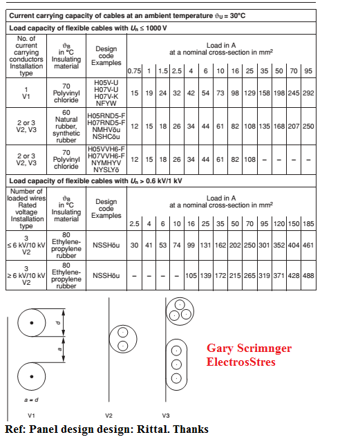
Popular methods of installation:
Method 2:
House wiring -
Single-core non
sheathed cables (wires) in metallic or no
metallic conduit on a wall or ceiling
Cables(wires)
in conduit embedded in masonry, brickwork, concrete, plaster or
the like (other than thermally insulating materials)
Single-core cables
in skirting or trunking
Method 3:
Sheathed cables (FTE) embedded
direct in
masonry, brickwork, concrete, plaster or
the like (other than thermally insulatingmaterials)
Sheathed cables
clipped direct to or lying
on a non-metallic surface or bunched
Grouping factors:
Grouping and number of cables on racks or trays (see table 6.14);
Grouping and number of cables in a trench (see table 6.15);
Grouping and number of cables buried directly in the ground (see tables
6.11, 6.12, 6.13 and 6.16);
Neutral imbalance (see table 6.17);
Harmonics (see table 6.18); and
Direct solar radiation (see table 6.19).
|
|
|
---------===============-------------
| |
|
|
| SANS: SANS
10142-1:2009 |
IEC |
|
Introduction
In this edition an attempt has been made to move towards the IEC codes:
extra low voltage (below 50 V) and d.c. applications (up to 1,5 kV) have
been
introduced as new requirements owing to the extensive usage of, and
increased fire risk that result from, high load currents. This part of
SANS 10142 does not intend to cover the LV control circuits of machinery or
system components that are external circuits between separately installed
parts of the machinery or system components.
This part of SANS 10142 includes certain provisions which are for
information and guidance only. These provisions do not use the word "shall"
and they can be found in the text, in the notes and in the informative
annexes. Except in tables, notes are always for information only. |
|
|
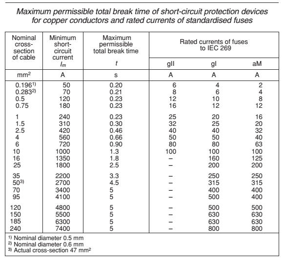
| Short Circuit Protection:
PSCC
6.7.3.2Unless other means of
short-circuit protection are used, a short-circuit
protective device shall be installed at any point where there is a change in
the characteristics of a conductor (such as a change in nominal
cross-sectional area).
NOTE Safe short-circuit protection of PVC insulated
copper cables will normally
be ensured if the cross-sectional area of the conductor (in millimetres
squared) is at least numerically equal to the prospective short-circuit
current (in kiloamperes).
This is based on a maximum
clearing time of less than one electrical cycle which is typical of LV
short-circuit protective devices. Amdt 6
6.7.3.3 With particular reference to socket-outlets and luminaire
supplies, the cross-sectional area of PVC insulated conductors shall comply
with the calculated prospective short-circuit current requirements (see also
the note to 6.7.3.2) for all points of consumption that fall within the
limits of 6.7.3.4. Amdt 3
6.7.3.4For the purpose of protection against
short-circuit current in PVC
insulated cables (of a cross-sectional area <4 mm
2), the first 5 m in
single-phase circuits and 10 m in multiphase circuits are
regarded as
being fault free. Amdt 3 |
|
|
| Plug sockets |
|
|
| Lighting |
|
|
| RCD 6.7.5.2
Industrial type single-phase and three-phase socket-outlets (including
"welding" socket-outlets) shall comply with the requirements of SANS 1239,
and, except as allowed in 6.7.5.5 and 7.10.1.6, shall have earth
leakage protection if the circuit is intended to supply portable or
stationary class I appliances. |
|
|
| |
|
|
-------------===========--------
Relationship between impulse withstand voltages of equipment
and over voltage categories.
| |
4.5.3.2.2 IEC 60 364 |
|
| |
Different categories of overvoltage exist for equipment.
category IV = for use at, or in the proximity of, the origin of the
installation, forexample, upstream of the main distribution board. Cat IV
has a very high impulse withstand capability providing the required high
degree of reliability.
NOTE: i) Examples of such equipment are electricity meters, primary
overcurrent protection devices and ripple control units.
Category III - for fixed installation downstream of, and including the main
distribution board, providing a high degree of availability.
NOTE: ii) Examples: DBs, circuit-breakers, wiring systems (see IEC
60050-826,
definition 826-15-01), including cables, bus-bars, junction boxes, switches,
socket-outlets) in the fixed installation, and equipment for industrial use
and some other equipment, e.g. stationary motors with permanent connection
to the fixed installation.
Category II = for connection to the fixed electrical installation, providing
a normal degree of availability normally required for current-using
equipment.
NOTE: iii) Examples: Household appliances and similar loads.
Category I is only suitable for use in the fixed installation of buildings
where protective means are applied outside the equipment –to limit transient
overvoltages to the specified level.
NOTE: iv) Examples of such equipment are those containing electronic
circuits like computers, appliances with electronic programmes, etc.
Category I equipment shall not have direct connection to a public supply
system |
|
| |
4.5.3.3.2.1 External hi voltage
influences: Where an installation is supplied by, or includes, an
overhead line, and the keraunic level of the location is greater than 25
days per year (AQ 2), protection against overvoltages of atmospheric
origin is required. The protection level of the protective device shall not
be higher than the level of
overvoltage category II, given in Table 44B. |
|
-----------=============---------
Earthing
| |
IEC |
|
| |
Machine safety: Ref: Panel design Rittal
Excerpt from VDE 0113-1/DIN
EN 60 204-1 and IEC 364-5-54,
543.1 or EN 60 439-1, 7.4.1.7, depending on
which applies.
Machine safety;
Electrical equipment of machines, general requirements 5.2 External PE
conductor connection
One terminal for
connecting the external PE conductor must be provided in the vicinity of the
corresponding external conductor contact.
The terminal must be dimensioned such that it
facilitates the connection of
an external copper conductor with a cross-section in accordance with the
following table.
If a PE conductor from a material other than copper is used, the terminal
size must be selected accordingly
Minimum cross-section of copper external PE conductor
also internal PE condiuctor most cases meet requirement if
the same as external
8.2.3 Continuity of the PE conductor system
All exposed conductive parts in the electrical equipment and the machine(s)
must be connected to the PE conductor system.
Unless no electrical mounted (or PELV used) lids, doors or cover plates must
also be connected (cannot depend on higes, screws) ,
If a part is removed for some reason (e.g. regular servicing), the PE
conductor system for the remaining parts must not be interrupted.
8.2.5 Parts which need not be connected to the PE
conductor
It is not necessary to connect exposed conductive parts to the PE conduc
tor system if these are mounted in such a way that they do not pose any risk
because:
– they cannot be contacted over a large area or surrounded by a
person’s hand and have small dimensions (less than approximately
50 mm x 50 mm)
or
– they are arranged in such a way that contact with active parts or an
insulation fault is unlikely.
This applies to small parts such as screws, rivets and identification
labels,
and to parts within enclosures, irrespective of their size (such as electro
magnets of contactors or relays, and mechanical parts of devices).
Labelling:
ONLY the terminal for the
external PE conductor labelled: “PE”.
Other terminals for PE labelled
with the EARTH symbol 417 IEC 5019 and 15.2.2.or
by using the two-colour combination GREEN/YELLOW.
8.2.7 PE
conductor connection points
All PE conductors must be connected in compliance with 15.1.1.
PE conductors must not be connected to connection parts used to secure or
connect devices or parts.
Each PE conductor connection point must be labelled as such using the
symbol 417-IEC-5019. Optionally, terminals for the connection of PE con
ductors may be indicated as such via the two-colour combination GREEN/
YELLOW.
Table 1
Minimum cross-section of copper external
PE conductor
Cross-section S
of external conductors
for mains connection
(mm2)
|
Minimum cross-section
of external PE conductor
(mm2) |
| S ≤ 16 |
S |
| 16< S ≤35 |
16 |
| S > 35 |
S/2 |
| |
|
|
|
------------------===============------
Enclosures:
For operator control requirement "controlsafety".
| |
IEC EN 60 529. |
|
| |
13.4 Enclosures, doors and openings
Locks used to secure doors and covers should be captive.
Windows intended for monitoring the display devices inside must be made from
a material
that is capable of withstanding mechanical stresses and chemical influences,
e.g. toughened glass, polycarbonate plates (3 mm thick).
We advise that enclosure doors should have vertical hinges, preferably of a
type where the doors can be lifted out.
The opening angle should be at least 95°.
The doors should be no wider than 0.9 m. |
|
| |
13.3 Minimum Protection categories
Enclosures of switchgear must have a minimum protection category of IP 54
(see EN 60 529).
Unless IP22 for Vented enclosures which only contain motor starter
resistors, dynamic braking resistors or similar equipment:
– IP23 for Motors
–IP 33 - Vented enclosures containing other equipment:. |
|
| |
Ref: Panel design Rittal 6.3. By using PELV
in accordance with 6.4, protection against both direct contact and indirect
contact is ensured.
6.2.3, must be applied to each circuit or each part of the electrical
equipment.
6.2.1 Protection via enclosures (housings) Active parts must be
positioned within enclosures which meet the relevant requirements from
sections 4, 13 and 16.
For top covers of enclosures that are readily accessible, protection
agains direct contact, protection category IP 4X or IP XXD, must be met as a
minimum requirement (see EN 60 529).
It must only be possible to open an enclosure (i.e. opening doors,
removing lids, covers and the like) if one of the following conditions is
met:
a) Use of a key or tool for access by electricians or electrical staff if
switching off the equipment is inappropriate. The master switch may be
switched with the door open, if necessary.
b) Disconnection of active parts within the enclosure before the
enclosure can be opened.
Door interlocking handle. Overide by special tool is allowed
and
– when the door is closed, the lock is automatically reactivated.
This is applicable to all entrances to the enclodure
---------=====-----
All parts which remain live after disconnection must provide protection
against direct contact, protection category IP 2X or IP XXB (see EN 60
529),
as a minimum requirement.
Such parts must be labelled with a warning notice in accordance with
18.2.
The mains connection terminals of the master switch are exempted from
this
ruling, provided the latter is housed in a separate enclosure.
c) Opening without using a key or tool and without deactivating the
active parts must only be possible if all active parts are protected against
direct contact in accordance with protection category IP 2X or IP XXB (see
EN 60 529) as a minimum requirement. If covers provide this protection, they
must either only be removed using a tool, or else they must automatically
deactivate all protected active parts when the cover is removed.
|
|
-------------===========--------
Wireways:
| IEC |
|
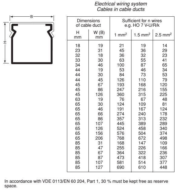 Ref: Panel design
Rittal |
|
| |
|
---------------==============---------------
Found this table from Panel design Rittal -
Further discussed under circuit breakers
---------------=============-------------
IP rating of panel see "Standards"
---------================--------
Enclosure mechanical protection: IK code
Ref: Panel design Rittal
Protection category to DIN EN 50 102, protection from external mechanical
loads (IK code)
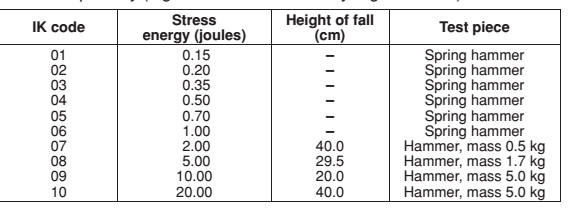
After testing, the test piece must be fully functional.
In particular, the protection category to EN 60 529 must not be impaired
(e.g. hinge bent, seal cut, gap in friction-locked connections or similar).
Safety and reliability must not be impaired.
----------------============----------------
Cables:
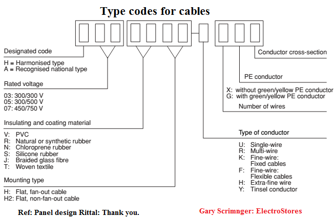
-----------------==============-----------
Cable ratings:
--------------==================-------------
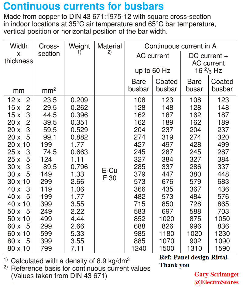
Busbar ratings Table 1
---------------==============-------------
Current correction for Cu busbar systems. Because of HOW we normally use
barsbar systems (in a panel etc)...we can use them at higher ratings.
In DIN 43 671 on measuring continuous current for copper busbars, Table 1
shows continuous currents which generate a busbar temperature of 65°C in
busbars of E-Cu with a square cross-section in internal installations at an air
temperature of 35°C.
For other temperature conditions, Figure 2 of DIN 43 671 shows a correction
factor which is multiplied by the original rated current to obtain the new
permissible rated current.
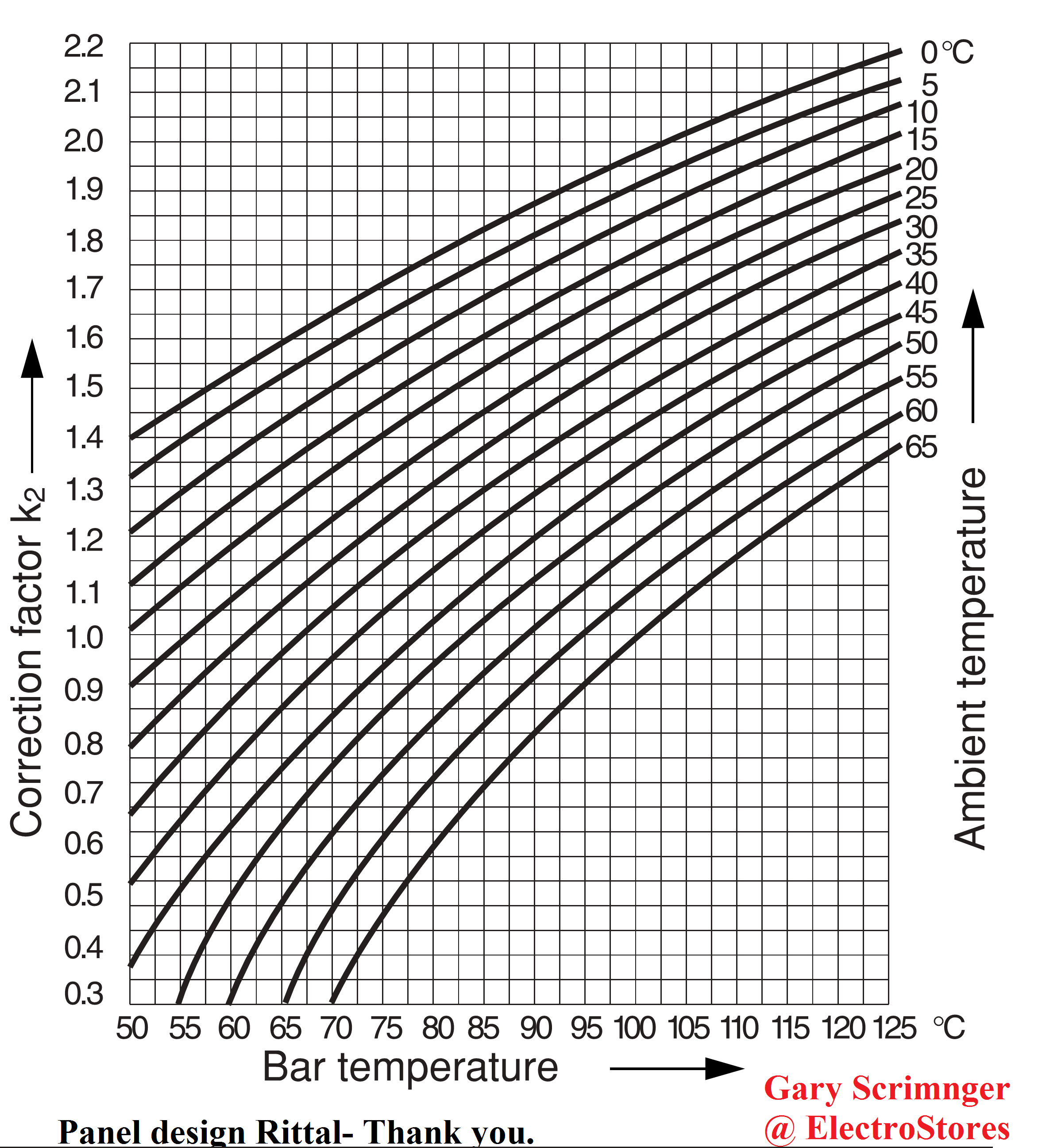
How to:
Bar cross-section 30 x 10 mm
Permissible bar temperature 85°C
Ambient temperature 35°C
From Figure 2 correction factor K2= 1.29
I1= IN * k2= 573 A * 1.29 = 740 A
To this end, 8 % = 60 A is added to the (assumed) more favourable emission
level of the bars, producing the new permissible rated current:
IN= I1+ I1 8/100 = 740 A + 60 A = 800 A
-----------======================-----------
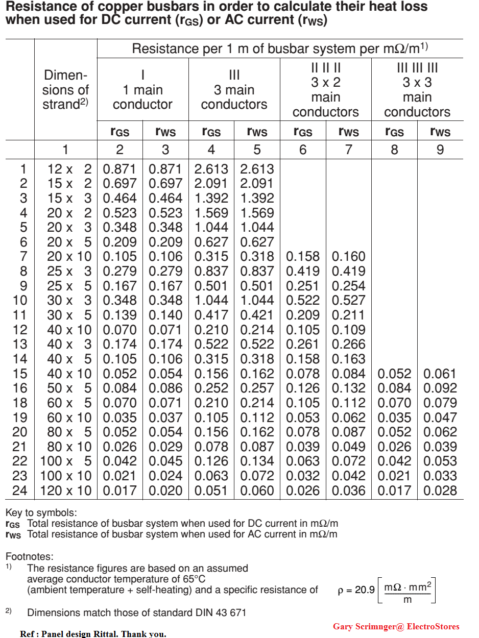
Busbar resistance table
----------================---------------
Re panel design and responsibilities:
Type testing:
Type tested: (TTA)The final product is un- modified from the manufacturer -as
was tested.
Partial Type tested (PTTA) e.g. A panel mnf by first party is completed by a
second party who has to also certify compliance.
"Type testing" in another context also imply that not every product is tested
eg a compliance testing facility. Only a sample was tested and so compliance has
to ensured by a different system eg ISO mnf procedures.
Panel design re standards:
| |
|
UL |
| |
|
Important notes for the use of
busbar
systems to UL 508
One of the principal changes in UL 508A is the amendment to the required
creepage
distances and clearances for feeder circuits.
The following
distances are required for applications > 250 V:
Between phases:
● Creepage distance 50.8 mm (2 inches)
● Clearance 25.4 mm (1 inch)
Between phase and earthed, uninsulated metal parts:
● Creepage distance 25.4 mm (1 inch)
● Clearance 25.4 mm (1 inch)
Rittal RiLine60 complies with these requirements.
However, users should bear in mind a small number
of differences from the IEC version:
● Special UL busbar supports for flat bars and Rittal PLS with increased
creepage distances and clearances.
● Use of the Rittal RiLine60 base tray is required in order to comply with
the necessary minimum distances from the mounting plate.
58
------------===============-------
1. Rated currents
For untested busbar applications, UL 508A specifies a current carrying
capacity of 1000A/inch2 (1.55 A/mm2) in the absence of testing.
This value may be higher if the product or application has undergone
suitable testing. Rittal has conducted extensive testing in this respect in
order to give users the maximum benefits when using the RiLine60 busbar
system. The benefit of such testing is that busbar systems with higher rated
currents may be used than permitted by the default value. For example, a
busbar with the dimensions 30 x 10 mm can carry 700 A instead of 465 A.
-=-----------------==============--------
2. Terminals for factory or field wiring
Terminal approved for factory wiring, it may only be used in switchgear
assembly by suitably trained professionals.
Approved for field wiring can only be used in the field (e.g. on a
construction site)
the component must be approved for field wiring.
-----------=============--------
|
------------=================-----------------
Panel SCCR - Short circuit Current Rating
| |
NEC/UL |
| |
Since 2006, all UL Listed industrial control panels are
now marked and labeled with a Short Circuit Current Rating
How to determine SCCR:
1: Test the panel at its labeled SCCR in a
witnessed test by a National Recognized Testing Lab (NRTL).
OR
2: Apply the standardized tables of UL 508 A,
standard for
industrial control panels.
Note: A panel SCCR can be increased by using current
limiting devices. Ref Littelfuse SCCR whitepaper.
|
---------------===============-------------

-------------===============--------------
Mixed loads: looks like they could not decide what IS a mixed load.
| SANS |
|
|
|
Intro notes:
6.16.1.1 Fixed appliances is not part of electrical
installation
When a fan is part of a luminaire it becomes an appliance.
-----
6.16.1.4 Where a fan or heater is
included in a luminaire, the luminaire is
regarded as a fixed appliance. If the luminaire
circuit is protected by earth
leakage, a disconnector is not required (see 6.9.3.1).Amdt 1 -
--------
6.16.1.3The power supply
to every fixed appliance, except
luminaires,
shall be supplied through
a) a disconnecting device that disconnects both live conductors in a
single-phase supply and all phase conductors in a multiphase supply,
or Amdt 3
b) a socket-outlet Amdt 3
that is directly accessible at all times that any person is exposed to such
appliance while the supply is on.
In the case of a remotely
installed
appliance, the position of the disconnecting device shall be indicated by
means of a notice in close proximity to or on the appliance. Amdt 3
6.15.4 Mixed loading of circuits NOT ALLOWED
| Mixed loads not
allowed but you can mix sockets, luminaires and fixed appliances.
Really? |
except as allowed in 6.15.4.2 and 6.15.4.3, there shall be
no mixed loading of circuits.
(See also 6.16.3.2.3.) Amdt 5
6.15.4.2
A single-phase circuit that has
overcurrent protection rated at not more than 20 A may supply a mixed load
of
a) socket-outlets rated at not more than 16 A and fixed
luminaires,
b) socket-outlets and fixed appliances, or
c) socket-outlets, luminaires and fixed appliances.
Why this strange list of A,B,C
NOTE The number of points need not be limited. I
don't think so, especially not mixed loads!
My take:
a) CB<=20Amp (domestic)
b and c) circuits bigger then 16Amp sockets and has
to comply with 6.7.5. and
NOTE 1 See 7.1 for the conditions under
which a socket-outlet may be installed in a bathroom.
NOTE 2 See 6.16.1.6 for the conditions under which a socket-outlet may be
used for the connection of fixed appliances.
Plug rating>=16Amp and fixed luminaires
EL Protection
|
|
|
-------------=============--------------
STANDARDS and references:
Why is the plug socket rating 16Amp and not 20Amp?
Why for a plug(feeder) circuit the circuit
breaker is 20Amp rated, the wire size is normally 2.5mm, but the sockets in
that circuit are 16Amps! What's up with that?
| SANS |
|
|
|
| 6.15.3 Single-phase circuits that
only supply socket-outlets rated at 16A
Single-phase
circuits that only supply socket-outlets rated at not more than 16 A,
a) shall have overcurrent protection;
b) shall use conductors that are rated at not less than 16 A;
c) shall, if the circuit
protection is rated at more than 20 A, use only protected
socket-outlets, with, as far as is practicable, discrimination between
the protective devices for the circuit and the protective devices
associated with the socket-outlets.
The protective
device of a protected socket-outlet shall
1) have a fixed rated current that does not exceed the rating of the
socket-outlet,
2) be mounted next to the socket-outlet that it protects,
3) provide protection against overload currents,
4) provide protection against short-circuit currents, unless
short-circuit protection is provided by a separate device, for example
on the distribution board,
5) if it needs the protection of a back-up short-circuit device, be
marked with the required or maximum rating of the back-up
device,
6) if it protects more than one socket-outlet, be so installed that all
the socket-outlets are connected in parallel, have the same rated
current, and are mounted next to the device, and
7) if it is a circuit-breaker, comply with the requirements of 6.8.2.
NOTE In the interest of safety, the use of the building, the
convenience of the occupants and the possibility of heating and cooling
equipment being connected to socket-outlets, should be considered when
the number and position of points of
consumption are being determined.
|
|
|
|
---------================----------
Test: Max volt drop - This has never been a test - its a calculation.
| SANS |
|
|
|
5.2.2 Voltage drop
5.2.2.1When all conductors of an a.c. installation are
carrying their
maximum estimated load, the difference in voltage (the voltage drop)
between the point of supply and any point of outlet or terminals of fixed
appliances shall not exceed 5 % of the standard voltage or of the
declared phase-to-neutral voltage (see also 6.2.7).
In the case where
reticulation is part of the electrical installation after the point of
supply, the
5 % voltage drop shall be calculated to include the reticulation part of the
installation (for example, in the case of a housing scheme where further
submetering with a further point of control is installed for individual
consumers).
Means: The maximum volt drop from the supply point
to the furtherst end of an installation shall be max 5% of Vsupply.
Same for DC |
|
|
| |
|
|
|