Technical


Home Electrical theory Acronyms Installation standards Capacitors SupplySystems Automation Sensors Controllers and modules Control and Safety MicroProcessor PCboard References About us

Home
Electrical theory 2
Drawings and symbols


Discovering electricity.

Special note:

We did not always know what we know today.

It was either discovered by someone or defined by someone, and one way of paying tribute, to say thank you, is to honour the discovery in the persons name.

I believe it is imperative to keep the story real and not just academic...


Prelude:

Just to put it in perspective...if magnetism, electricity and electromagnetism was not discovered when it was discovered, all technology as we know it would not have been.

No electricity...nothing.

I think this civilisation would have progressed very differently...we would been cleverer but with a different mentality.

In ancient history - all around the globe - some successful civilisations was extremely clever in the way mega-buildings was constructed that we cannot replicate today...and they had no electricity.

That's the different mentality I am referring to.

And in the beginning...

Surely, first we discovered magnetic material and seen the affect this load stone has with respect to the earth. When in floating suspension it always points in the same direction.

The next logic to follow is that the earth must have invisible forces between the earth and the special stone to attract one specific end of the stone. It makes perfect sense that it shall be called "magnetism", since that is exactly what magnetism means.

And since that direction was already called "north" by some old language, meaning "left when facing the rising sun"...it became the north pole even in magnetism. Cool hey.

--------

--------


And finally our story really starts...

The beginning of electricity:

In the year 1800 the first battery ever is presented to Napoleon Bonaparte and the world changes.

At that time it was the believe that frog legs and metal rods creates electricity. To prove a point that this was not true Mr. Volta built the first electrical "generator" which we can say is a battery.

And this is how it came to be that he held a demonstration for Mr. Napoleon Bonaparte...starting a new evolution in technology that will soon touch each and every person on this planet. Amazing.

And for his great incidental work the unit for a potential difference (electricity) is named after him....VOLTS. 

He also defined capacitance with "Volta's Law of Capacitance".


His Work:

If we achieve a potential difference between two points then electricity is created electricity.

The nicest explanation I have found to explain potential difference is from my "Electrical Trade Theory" handbook by C. du Preez.

If one end of a copper wire is heated and the other remains cold then there is a "potential" for the heated point to transfer to the cold area.

Likewise for electricity:- If between any two points there is a higher charge than the other, then a potential difference exist between them. We measure this in volts.


Definition of a volt: The difference of electrical potential between two points on a conductor when a current of 1Amp flows and the power dissipated is 1Watt.


Volta's law of capacitance law:

Capacitance = Q(charge stored)/V(voltage applied)

This is much better explained if we change the equation to: Q = V * C

The voltage and the capacitance is directly proportional to the final charge(Q).

tba Gary


Since we are on the roll about naming conventions...where does the notion of "current" in electricity come from?

The first clue is that we say electricity "flows" - yet it is not flowing anywhere. We might be passing electrons but that is as far as it goes.

So, in this time in history and prior - it was still taken for granted that electricity is a fluid...really!

And since a fluid flows, so electricity must also flow...and thus it flows like a river in the wire...and anything that flows has a current.

What a cool reveal that was!


We have done "current" but what about "charge", where does that come from?

I suspect in Mr. Ben Franklin's time already it was deduced, from his kite experiment (which proved lightning is also electricity), that one part (the clouds) gets charged with something and the other not (the earth), and so it , quite correctly, acquires a potential difference said to have a "charge".


It was by now known that if current flows something happens...but how to understand it, to make sense from it?

Mathematician, school teacher.

Next to Mr. Volta, Mr. Ohm is probably the best known surnames in the electrical world - unit of resistance and two laws directly carries his name.

All electricity 101 classes start with his lectures.

The electrochemical cell, invented by Italian scientist Alessandro Volta is what got Mr. Ohm started.

Using this volt-cell as a supply with his own invented equipment Mr. Ohm came to realise the relationships between volts, amps and resistance.

Remember: - Electricity as we know it today does not exist yet...they are only playing with batteries here.


His work:

V=I*R i.e. I=V/R i.e. R=V/I

What Mr. Ohm realised is that there is something in the wiring circuit and that something causes ONLY a specific current to flow according to its value. It phantomly controls the current - it is "resisting" the full current to flow...and without further redo named it "resistance".

He discovered was for a specific applied voltage the current changes as a function of the circuit resistance. Hence: V = IR

But Gary...where does that R fit in?

We can also say: If, for an applied voltage of 1Volt, results in a current flow of 1Amp then the resistance of the circuit will be found to be 1 Ohm. Thus R=V/I.

Yes that makes much more sense.

In this equation lies the proof that the circuit must have a certain characteristic and Mr. Ohm called it "resistance".


This earned him the unit of resistance named after him.

Lucky for us its a short German surname.


--------------============---------

Info note:

It has come to be that the electronics industry is built on the principles of understanding the beauty of resistance and therefore has a full range of resistors in varying wattages, for without this electronics, as we know it, could not exist.

Oh, by the way...nowadays we can measure resistance with a meter.

We have also developed a code to indicate the resistance value.

When I was just a appy I came up with this rhyme to remember the values of the colours:

Black Broy gave Bev a grey whip

Value Value Multiplier Tolerance band is the last band. There is a space between to the second last band to indicate direction.
0 Black black Not used
1 B... brown 1
2 R... Red 2
3 O... Orange 0.05


4 Y.... yellow 0.02


5 Gave green 0.5


6 Be... Blue 0.25
7 V...a Voilet 0.1
8 Grey Grey 0.01
9 Whip White not used
      Silver= 10%
      Gold=5% (most common)
      No colour=20%

- See if you can figure how the code work from this clue:  1000 Ohms   Colours: Brown Black Red

Now one would have thought that's the end of it...but there is a much more complicated "new" system out there which I'm not going

to cover...it's for special low tolerances and military spec resistors. I seldom encounter and never had to use them...thankfully.

Now back to work:


---------------=========---------------


So far we only have half the story to our successful civilisation...

Mr. Oersted brought the other half.

We knew about magnetism at this time - apparently even a book or two was written about it

- but the only work we could find for it, so far, was in the compass for navigation purposes.


......

In Denmark - a country in the strange tip of northern Europe - Mr Oersted powered a wire circuit with Mr. Volta's cell and noticed, whether by accident or not, that it caused a compass needle to deflect and point perpendicular to the wire.

And if the supply around (positive and negative), it deflected the opposite way.

He must have thought there was ghosts in the room...through the air it can talk to the compass needle.

He discovered the connection between electric current and magnetism, and  "electromagnetism" was born.

Ps: A close friend of Hans Christian Andersen (if you are into fairy tales you will know about him) also his brother was the Prime Minister of Denmark.

His Work:

Rule 1: For a straight conductor pointing away from us - if we allow a conductor current to also flow away from us (north closest to us - conventional current) a circular magnetic field around the wire and in a clockwise direction.

To make it easy to remember we use the left hand rule. In a fist grasping a current carrying conductor, if the thumb point towards the positive of the supply (the direction electrons are flowing) the rest of the fingers will in the field direction.

Rule 2: If a current carrying conductor is coiled (looped) it creates a magnetic field around the coil with lines entering the bottom opening (south pole) - which is also the entry side for the conductor current flow - and exiting top opening (north pole). 

Rule 3: The field strength is proportional to the amount of current.

Rule 4: In a coiled wire (solenoid) the more coils(loops) the stronger the field.

What is the right hand rule.

Well a mix-up occurred.

Benjamin Franklin (1705–1790) - yes, a previous president of the USA - was also an inventor and the first to ascertain that lightning is also a form of electricity and he "theorised" the direction to be positive to negative. Nowadays it is referred to "conventional current flow".

A couple of hundred years later it was realised the electrons actually flow opposite...negative to positive.

So - I don't know who is scared of who - but the wrong way persists, so now we have the right hand rule and the left hand rule.

If you are young then I suggest you only remember the left hand rule and just remember the right hand rule is the opposite (it might just get fixed then you are already on the right track)..       

And don't tell anyone the right hand rule is wrong...you know, we don't want something to happen to you now - just say it is for conventional current flow. 


I guess this caused a frenzy to figure out what was the strange ghostly  forces...and soon back in France.

Personal note: Contemporaries sometimes lead one to believe that Mr. Ampere had some sort of mathematical impairment or limitation because of his "home schooled background" - until one reads of the nature and the man  "Makers of Electricity" by Brother Potamian and James J. Walsh 1909.

I am so grateful for project Gutenburg to have had this in their library.

If one wants to undermine your own intelligence then read this piece and feel what I felt. 

From his work we now have:- Ampère's force law, Ampère's right hand grip rule, Avogadro-Ampère hypothesis.

Inventor of the solenoid (a term coined by him) and the electrical telegraph.


Work: If two current carrying conductors are placed parallel to one another, there will be a force exerted between the two conductors.

If a current carrying conductor is brought into a magnetic field a force exerted this conductor, causing it to move.

If the currents flow in the same direction the field will be stronger (added) and attract each other.

If the current flows are opposite then the field will work against each other (subtract) and repel each other. 

The left hand rule also applies here - (but you said the right hand rule in the heading)

The pic explains many things - if one grasps it, including the hand rules.

Ampere definition: In a vacuum, if two conductor are placed in parallel, 1 meter apart then as force of 2 x 10e7 Newton per meter of length will be exerted on the conductors.  


Info-note: Just an additional note that troubled me at the time of writing.

To the clever ones who practice integration:

I have come across many educational institutions that claim that in two parallel wires with opposite flowing currents having intersecting electromagnetic fields, the fields cancel out one another?

Really, why is that not what I see in my head?

In my head I see the two fields - having abundance of the same charge (positive or negative) therefore they cannot equalise in anyway, meaning they cannot occupy the same space, this will have the repelling affect as we are familiar in magnetism. The fields will compact between the wires and balloon out on the extremities.

If they were cancelling out I don't think we would experience any repelling force between the wires.

But then I thought...Of course if one was to put a ferro - metal close to the north or south pole of the contraption it would seem there is no magnetic force - but that's not because its not there?

Ahhh, maybe from that perspective we say it cancels out, the magnetic force is decreased to nothing.

Though my point still stands...but I guess we will never know since these lines don't really exist...only the effects of it is observable.

So to the clever guys...or does the fields diminish. (cancel out?)


So now we know what electrical fields do, but what happens when a current carrying conductor is placed in the field of a magnet? 

This answer was provided by Mr. Michael Faraday 


-----------=============-------------


Then the real breakthrough discovery. So much so that it is said that Mr. Einstein kept a picture of this man on his wall...now that is a real show of recognition, isn't it?

Mr. Michael Faraday brought it all into practical use and open the doors to our new civilisation the way it is today. He opened the door.

And all that from someone with no formal education...apparently only "basic algebra" knowledge.

---

His birth-year 1791 - In 1991 it has been 200 years ONLY!

Mr. Faraday discovered "electrical induction " and completed the work with just about all prominent uses, as is it is today.

From the transformer to the electrical motor, so one can safely say he was the first electrician.


Whenever we hear induction, we should reflect back and say: Thank you Mr. Faraday.

---

PS: Why "induction"?

The word induce mean to persuade or influence to some action...

If two magnetic / electrical fields intersect either via the air or via an iron core that concentrates the fields (transformers) then we say the one field winding induces an emf in the other winding.

And so "induce" resulted in it being called "electrical induction"

Pretty logical,, wouldn't you say?


---


This was the big breakthrough - the stage for the real beginning of the electrical evolution was set.
 

The clever professors of those days had pretty elaborate experiment equipment but here is an electricians (DIY / backyard) version proving the concepts of electro-magnetism.

There we go...it moves pretty strongly with the starter motor current.

The "flexible wire" is 2.5 mm2 cab tyre with enough slack to move in all directions. 

But what do we get from this experiment mostly?

If you noticed the change in direction of the hands and the after effects then the mission is accomplished!

The direction of forces changes if any field direction changes (the magnet or the current).

This is also a beautiful example of how the hand can be used to remember the direction of the fields.

*In those days it was the right hand rule, so to avoid confusing I stick with the left hand only. If you are in the acedemia just remember the right hand is opposite and the thumb points to the wrong negative pole..

---

Work:

Understanding the nature of the dynamics of magnetic and electric -fields (Elementary/ Basic):


But what if we looped this same wire?

and what if we looped it many times?

That's when the realisation came that electro-magnetism took on the same characteristics of a magnetic field.

---

When I saw this result from professor  it made perfect sense and it became the basis of my understanding of it.

---


---


---

By now we know what was electricity and magnetism and the connection but how do we quantify such an invisible force?.

How strong is strong?


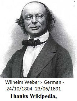
Wilhelm Eduard Weber: German Doctor. 1804 – 1891

First use of c for speed of light
Work on magnetism
Electrodynamometer
Telegraphy

His work:

Mr Weber (I call him doctor induction) created a platform for us to quantify magnetic fields.

He made it possible for scientists and electricians alike to understand the relationship between electricity and magnetism.

Like his hand rule:

***This is a slight modification from the left-hand rule we already know. As soon as you get it - you will never forget it.  

Easy one: Grab a coil with the left hand, with the fingers pointing in the direction of the coil's current flow then the the thumb will be pointing to the north pole (the direction of the flux flow)

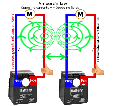
Complicated one: Grab a coil with the right hand and the fingers pointing to CONVENTIONAL CURRENT FLOW then the thumb will be pointing to the north pole of the electric field. 

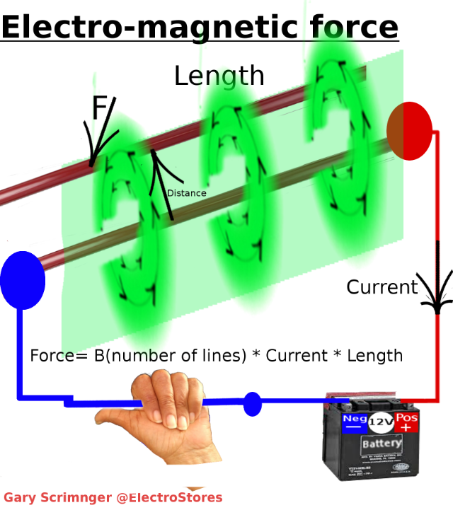
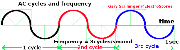
In order to visualise the invisible force we needed a unit to quantify the electrical force field...He called it flux.

Why?  

The word flux literally means: "to flow / emanate from" and / or "an unsure state of change". This is exactly how the electro-motive-force can be described.

And in his honour...flux is measured in Weber(Wb).

Definition: A weber ( Φ or ΦB ) is the magnetic flux when linking a circuit of 1 turn produces an emf of 1Volt in it, when it is is uniformly reduced to zero over 1sec.

---

Note of note: Next time you switch on the lights, or open the water tap...say thank you to Mr. Nikola Tesla for his great work and determination - I could nearly say sacrifice - from the stories I read about him - made it all possible. 

---

To get there we have to start right at the beginning:

 The chemistry of all things...

But before we start - just by the way - since it is so intriguing: -

According to contemporaries - Matter is anything and everything that is(exist).

The smallest identifiable part of matter is a molecule. So one can say matter is made up of molecules.

The smallest identifiable part of a molecule is an atom. So one can say molecules are made up of different atoms.

In the atom the electrons - like the planets of a galaxy - orbit a nucleus (the sun).

How big are atoms - (0.1 to 0.5nm), i.e.  a million times smaller then diameter of a human hair (0.1mm) strand.

I also saw a reference where it is said that 99.999999999999% of an atom's volume is empty! Nothing. One would wonder what keeps it all together.

The electron inner orbits are spherical but as the distance grow the pathways becomes less predictable.

The electron cloud has a radius 10,000 times greater than the nucleus.

The nucleus is made up of protons (and now neutrons).

From more than one resource it was said that a proton mass is approximately 1800 times that of a neutron. The neutrons mass is slightly higher than a proton.

Apparently and more spectacularly the electron, for hydrogen, are spinning around the nucleus at 2.2 km/sec.

The arrangement and quantities of these elements (electrons/protons/neutrons) determine ALL chemical elements. For the chemists this is their bread and butter.

And this is where it gets  interesting for the electrician: The electrons are negatively charged and the protons are positively charged. The neutron don't want to be part of the game, they are "neutral".

Electrostatics:

At atomic level the movement of the electrons makes up the characteristics of the different material such as when there is equals electrons and protons it carries no charge - the natural state of materials - unless it is a magnet!

The nucleus is held together by the tight pull of what is known to chemists and physicists as the "strong force."


On the other hand the the negative electrons is attracted to the nucleus (opposites attract) and nucleus is known as the electrostatic force.

This effect of opposites attract and similar charges repel each other is referred to as the First Law of Electrostatics.

For some materials - such as copper - An applied emf will dislodge electrons in a specific direction from atom to atom and this is our flow of electricity and from this various other forms of energies can be derived. 

What is an electrical charge?

When I found this information it just blew me away...it is not the norm in the educational system... yet I believe it is the "more truer" version of the definition of units and measurements.

An object’s electrical charge is determined by the number of electrons that the object has gained or lost. Because such a large number of electrons move, a unit called the "coulomb" is used to indicate the charge.

One coulomb is equal to 6.28 x 10e18(billion, billion) electrons.

For example, if an object gains one coulomb of negative charge, it has gained 6,280,000,000,000,000,000 extra electrons.

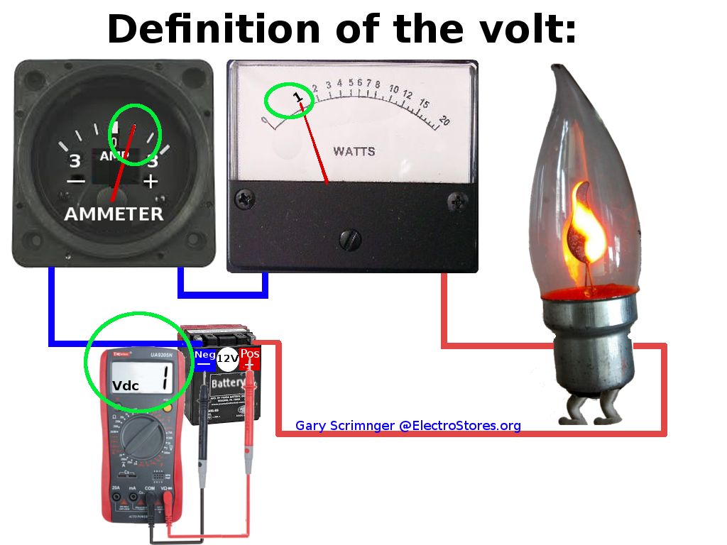
More conventionally : A volt is defined as a difference of potential causing one coulomb of current to do one joule of work.

A volt is also defined as that amount of force required to force one ampere of current through one ohm of resistance.

Force in the physical world and how they relate to the electrical world - Mr.Newton

Math visualisation - How we "formulate" formulas using our imagination. 


---


----


----

In the electrical world:

Now we need to put on the thinking hat, for all the work from all our scientists is coming to fruition in the maths of things. For a scientist if it cannot be proven via the maths then its not a fact yet.

We can see all the effect of magnetic forces but can we prove it by calculation?

I get the impression this is what Mr. Maxwell was good at - he could see the maths in things.

The stronger the magnetic field the more force it seems to be able to exert...so lets start there. We need a way to define that force (Newtons) that we see magnetic filed at work.

We say flux is that that generates 1V, but we don't know how big, it could be as big as a house or as small as a hair and still it provide 1V.

If we want to calculate the effects of flux, we need a better way to define this flux.

It does not really have lines but what if we said: The flux per a particular area - after all it will give us an idea of how concentrated it is...which is a function of the force it presents. Now that is a great idea. 

Flux by itself means nothing much...but if we can define its concentrate per area that is the function of its force...so:

Flux density B = Flux / Area =    Φ / m2 - and in order to pay tribute to the great inventor Mr. Nikola Tesla - the unit of flux density is Tesla (T).

---

---

What will be the force on a conductor if we placed it in the electro-magnetic field of another conductor (the field intersecting perpendicular only)?

Three factors come into play:

  1. How strong is the magnetic field it finds itself in - i.e. flux density.
  2. How much current is flowing in the conductor - this determines its own field strength
  3. and the length of the conductor in the field.

---
Personal note: This formula is just an indicator of how we arrived at the maths at a particular point and it only accounts for right angled (perpendicular) intersections but in reality it is a combination of also cutting at different angles meaning much less mmf is generatedat those angles.

Such that force become F = BLI sin θ  (θ  the cutting angle)


---

For simplicity sake we continue with the basic formula: F = Bil Newtons (To remember say: Fbill ?)

This is also true for the magnetic circuit where the magnetising force (H) at a specific point in the field will be a specific force and it will also be equal to:

H = IN/L amps/mtr

I = The current that creates the force.

N = number of turns

L = length of the magnetic circuit

*some letters should be in small caps but it will create confusion in this doc.


---

Electrically Magnetically
Energy =  Force * distance =  then we can say if the conductor moved x d distance

emf = F * d joules.

and if we bring in the time it took


The "result of electricity" in terms of the work or the effects it creates (meaning the effect on the electrons) is directly proportional to:

1: The applied voltage and

2: The amount of current in the circuit.

So the formula for work is F =  V * I and is measured in watt.      

Is power work done?

No. Power is that what is required to sustain a (re)action.

Work done is a measure of much energy was consumed/used/exerted over a period of time...we will still get there.


We also the the weber is the flux (Φ) LINKAGE that generates emf of 1V in 1 sec so:

Weber = flux  = V * t

i.e V = weber / t or more specifically V = dΦ /dt

So far we have assumed on conductor but what if e start having more then one conductor:

emf V = Number of conductors * dΦ /dt =  d(N*Φ)/t Volt


Power = VI Watts If work done is force over distance (Joule) the if our above conductor moved any distance we can say:

Work done = F * d N.m.

i.e. Wd = BIL * d

But energy = WD /sec so if our conductor moved over 1 sec then suddenly we know how much energy was exerted.

i.e. Power = BIL * d/sec

Oh, but hang on ...d/sec =  mtr/sec = velocity!

So Power = BILv Watt


---

If we say: Magnetic Power = Electrical power

BILv = VI

Cancel the currents and we have: V = BLv volts.

*It is imperative to remember that this is for ONE CONDUCTOR  cutting the magnetic lines - we worked on the premise of the definition of a Weber.

For a coil Total emf = BLv * number of turns volts(N).

It is also imperative to remember this formula only accounts for perpendicular crossing (maximum) of the magnetic lines.

In reality magnetic lines are crossed according to the sine of the angle meaning the instantaneous values would be emf = BLvN * sin Φ volts - that angle at that particular time.

So now we can generate AC wave forms:


---

So far for this formula emf = BLv*(N) we have one conductor and it moves linearly

We have to improve it to cover a rotating conductor and also for a looped conductor . The v in this formula implies linear movement (distance) for a motor we have to relate the formula in rotational velocity.

The L also represent a straight one conductor 

See here to perfectly understand the concepts of calculations in circles as used in the AC waveform.

See here for the graphical representation of the AC wave form.

We are now interested to find out how fast our waveform is being formed, and this is where radians comes to our rescue with angular velocity.

Linear velocity (v) = m/s but in terms of radians the distance per revolution (angular velocity) would be 2*Pi thus 2 * Pi /time for one revolution.

For multiple revolutions = 2Pi * number of revolutions/sec (n).

v = 2 * Pi * n   rev/sec

emf = BL(2*Pi*n/sec) N * sin Φ volts = 2Pi*BLnN/time sinΦ volt

Now we have to improve L.

A loop can be calculated as total length + width(w) and this is the same as the area formula(A) the loop forms.

e = 2Pi*B(L*w)* n * N sinΦ volt

The total emf generated at a specific instance (instantaneous value) during the rotation of a COILL:  e = 2Pi*BA* n * N sinΦ volt and the result always completes an alternating sine wave form.


Frequency = number of cycles per second = 1/time.

A cycle is one complete positive +negative part of the waveform.

And this is where the mains frequency of 50 hz (Europe) and 60 Hertz (America) comes from.


---

Lets just bring a few electricians formulas to life here...normally we just use the end products of:

Average value of a PURE AC wave form = 0.636 Max value

and 0.707Max value is the RMS value...

Ask an electrician where this comes from and a shrug might be the best answer.

So Average value:

It is at it is in maths: Add the number of points you want to average and divide it by the qty of these points. Lets say current:

Iave = (i1+ i2+i3+in)/n (the number of instantaneous values one cares to calculate)

By the way : If we took the average over a PURE full cycle what will the answer be : 0...they will equal out. So we only calculate over half a cycle.

For my tests I made Imax = 100 - so one gets an impression of percentage.

At only 90Degree peak value it is 100/2 = 50. That's way off from 0.636?

Then I tried it at 30degree intervals - answer 62.20084679...closer but not there yet.

Then I tried it at 10 degree intervals. Answer = 63.50029057

And at 5degree intervals: Answer = 63.62157097


---

Av at 5deg 0 1 2 3 4 5 6 7 8 9 10 11 12 13 14 15 16 17 18
Angle 0 5.000 10.000 15.000 20.000 25.000 30.000 35.000 40.000 45.000 50.000 55.000 60.000 65.000 70.000 75.000 80.000 85.000 90.000
Factor 0.000 0.087 0.174 0.259 0.342 0.423 0.500 0.574 0.643 0.707 0.766 0.819 0.866 0.906 0.940 0.966 0.985 0.996 1.000
                                       
V1peak 100.000 100.000 100.000 100.000 100.000 100.000 100.000 100.000 100.000 100.000 100.000 100.000 100.000 100.000 100.000 100.000 100.000 100.000 100.000
v for V1   8.716 17.365 25.882 34.202 42.262 50.000 57.358 64.279 70.711 76.604 81.915 86.603 90.631 93.969 96.593 98.481 99.619 100.000


Av at 5deg   19 20 21 22 23 24 25 26 27 28 29 30 31 32 33 34 35 36
Angle   95.000 100.000 105.000 110.000 115.000 120.000 125.000 130.000 135.000 140.000 145.000 150.000 155.000 160.000 165.000 170.000 175.000 180.000
Factor   0.996 0.985 0.966 0.940 0.906 0.866 0.819 0.766 0.707 0.643 0.574 0.500 0.423 0.342 0.259 0.174 0.087 0.000
                                       
V1peak   100.000 100.000 100.000 100.000 100.000 100.000 100.000 100.000 100.000 100.000 100.000 100.000 100.000 100.000 100.000 100.000 100.000 100.000
v for V1   99.619 98.481 96.593 93.969 90.631 86.603 81.915 76.604 70.711 64.279 57.358 50.000 42.262 34.202 25.882 17.365 8.716 0.000
  Results                                    
  Sum 2290.377                                  
    36                                  
    63.62157                                  
  Percent 0.636216                                  


---

It is clear the closer intervals I use the closer I get to the general accepted factor of 0.636.

Why did I do this?

I found  2/Pi arrive at 0.636....why?

This was arrived at by using calculus.

Calculus is a method (tool) to calculate to the smallest possible increment...which is exactly what we are looking for in our averaging venture.

In this case the total half cycle (remember why only half cycle: they cancel out over a full cycle) are is calculated and then divided by the smallest incriment (that is the length of the half cycle).

The area of say the positive cycle is:

A = ⌠Pi i . dΦ

      ⌡0


a = ⌠Pi i . dΦ .....

      ⌡0

= Max * ⌠Pi  sinΦ .dΦ

             ⌡0

= -Max * [cosΦ] between Pi and 0

= - Max * [-1-1]

=2Max in Ampere-radians

*See calculus for base information (hopefully I can find  a maths fundi volunteer one day)

If we know the area is 2Max
and we know the length is Pi...see here why?      


We have a calculation: Average = 2Max/Pi.

which result in:

Iaverage = 0.636 * Imax or

Vaverage = 0.636 * Vmax

Do not forget these are for pure (proper) sine waves only.


---


Now the famous one...

The standard AC voltages 220V or 110V or 400V - where does it all come from?

Even better - When we meter an AC circuit we measure these standard values...But if the supply is a waveform meaning it is not stable (static) then what exactly are we measuring.

When we purchase electricity it is not measured on the basis of average or peak but on the basis of the work it does for us. 

When we size and electrical appliance it is on the basis of the kiloWatt it can deliver for us. It is for this reason we need a method to measure the work an AC supply can deliver for us.

There we go again with our average for the AC waveform, but this time on the premise of power.

Thus: P = VI = I2R(i12 * R  +  i12 * R +  i22 * R +  i32 * R +  in2 * R)/n

But R is the same at all times so:

I2 = (i12  +  i12 +  i22 +  i32 +  in2)/n

I don't know if the mathematics quadratic formula exist from this or from some other spectrum but it is called the quadratic formula...and on this basis electricians call it the ROOT MEANS SQUARE.

Now I am an electrician and uses this everyday of my life, like forever, so when I hear this value it causes a tingling in my spirit. Exciting stuff.

The RMS value is the value we all use and gets invoiced against.

I did the actual calculations...


---

    1.00 2.00 3.00 4.00 5.00 6.00 7.00 8.00 9.00 10.00 11.00 12.00 13.00 14.00 15.00 16.00 17.00 18.00
Av at 5deg                                      
Angle 0.00 5.00 10.00 15.00 20.00 25.00 30.00 35.00 40.00 45.00 50.00 55.00 60.00 65.00 70.00 75.00 80.00 85.00 90.00
Factor 0.00 0.09 0.17 0.26 0.34 0.42 0.50 0.57 0.64 0.71 0.77 0.82 0.87 0.91 0.94 0.97 0.98 1.00 1.00
                                       
V1peak 100.00 100.00 100.00 100.00 100.00 100.00 100.00 100.00 100.00 100.00 100.00 100.00 100.00 100.00 100.00 100.00 100.00 100.00 100.00
v for V1   8.72 17.36 25.88 34.20 42.26 50.00 57.36 64.28 70.71 76.60 81.92 86.60 90.63 93.97 96.59 98.48 99.62 100.00
                                       
    75.96 301.54 669.87 1169.78 1786.06 2500.00 3289.90 4131.76 5000.00 5868.24 6710.10 7500.00 8213.94 8830.22 9330.13 9698.46 9924.04 10000.00


    19.00 20.00 21.00 22.00 23.00 24.00 25.00 26.00 27.00 28.00 29.00 30.00 31.00 32.00 33.00 34.00 35.00 36.00
Av at 5deg                                      
Angle   95.00 100.00 105.00 110.00 115.00 120.00 125.00 130.00 135.00 140.00 145.00 150.00 155.00 160.00 165.00 170.00 175.00 180.00
Factor   1.00 0.98 0.97 0.94 0.91 0.87 0.82 0.77 0.71 0.64 0.57 0.50 0.42 0.34 0.26 0.17 0.09 0.00
                                       
V1peak   100.00 100.00 100.00 100.00 100.00 100.00 100.00 100.00 100.00 100.00 100.00 100.00 100.00 100.00 100.00 100.00 100.00 100.00
v for V1   99.62 98.48 96.59 93.97 90.63 86.60 81.92 76.60 70.71 64.28 57.36 50.00 42.26 34.20 25.88 17.36 8.72 0.00
                                       
    9924.04 9698.46 9330.13 8830.22 8213.94 7500.00 6710.10 5868.24 5000.00 4131.76 3289.90 2500.00 1786.06 1169.78 669.87 301.54 75.96 0.00
                                       
  RESULTS                                    
  Sum 180000.00                                  
  No points 36.00                                  
  to square root 5000.00                                  
  Calculation 70.711                                  
                                       
  RMS formula 0.707                                  
 

----

And we arrive at our 0.707 as a percentage factor to calculate RMS value. 

But just in case we hear the words: "What will I ever need calculus for in life?" - Here is another example of its eloquence.

From our previous average calculation we know 

Average = Pi/2 * Max

i.e for Iave = Pi/2 * Imax

In terms of power it will be P = I2 * R = 2/Pi * (imax2) R - the power area of the curve.

to calculate the average for power on a half cycle:   [2/Pi * (imax2) R]/Pi

since R same on left and right they cancel...and the Pui cancels

and we simplify the quadrature

I2 = 2/Pi * (imax2)

Iave  = Imax/√2

= 0.707 Imax


Just a few other electrical know-hows:

To calculate the peak value from RMS: Peak = 1/0.707 * RMS

Form factor =0.707/0.636 =1.11


Charles-Augustin de Coulomb - French(1736 - 1806)

Completed the description of the electrostatic force.

Coulomb's law states that: 'The magnitude of the electrostatic force of attraction or repulsion between two point charges is directly proportional to:

1: The product of the magnitudes of charges

2: and inversely proportional to the square of the distance between them.

If charges of the same polarity repel each other; charges of opposite polarity attract each other.

F = k * (q1*q2/d2*d can be r - it is just the distance between the conductors.

k = Coulomb constant 9×10⁹ N.m2.C−2

q1 and q2 the charges

r = d = distance between the charges

---


---

must respond to this:

https://girlsangle.wordpress.com/2013/07/31/why-does-the-area-under-one-hump-of-a-sine-curve-exactly-equal-2/


Between a coil (looped conductor) and the created flux the strength and respective resulting motions are a direct result of:
bulletHow fast the respective movement,
bulletThe strength (density) of the field,
bulletAnd relative size of the conductor to the field.


To do:

Amperes formulas:


 Charge: Q = I.t Coulomb


---

See psychology - just check it!

See the "Series and parallel anecdote".

----------------------------

Understanding the parallel resistance:

In a parallel connection all connections (resistances) are at rail voltage, this means the voltage is the same for all circuits.

For each circuit we can then say: Ix = V/Rx

We also know that It (the total current to the circuit) = The sum of all the branch circuit currents, ie. It = I1 +I2 +In

Therefore: V/Rt = V/R1 + V/R2 + V/In...

We can simplify this by the V on the left cancel out with V on right.

AND WE ARE LEFT WITH:    

Total parallel resistance formula: 1/Rt = 1/R1 + 1/R2 +1/Rn

-----

Series calculations:

Vt = V1+ V2+ Vn 

ie I*Rt = I*R1 + I*R2 + I*Rn

and if the I cancels out on left and right then:

Series total resistance: Rt = R1 + R2 + Rn 


---

The beginnings of AC (Alternating current)

I think this page is too long so we will continue on basics2


---

Interesting websites:

This is guaranteed the most entertaining web source regarding this topic: https://particleadventure.org/index.html

I have to add this link - it might change someone's mind about his/her destiny : https://www.cpepphysics.org/


-----------

 Also see here for our very extensive topic list of discussions.


References: Thank you to the following who unwittingly or wittingly collaborated to build knowledge. For any infringements, apologies. Let us know here:

Copyright issues