Technical


Home Up Acronyms Installation standards Capacitors SupplySystems Automation Sensors Controllers and modules Control and Safety MicroProcessor PCboard References About us

Home
Up
Acronyms
Installation standards
Capacitors
SupplySystems
Automation
Sensors
Controllers and modules
Control and Safety
MicroProcessor
PCboard
References
About us


------

The beginnings of AC (Alternating current)

Isn't it funny that we don't say alternating voltage or alternating supply? I've been taught it to be AC and that's it. Strange. 

Don't forget to mention that we call it a sinusoidal waveform for a reason.

Why do we even have radians or angular solutions...it just confuses the hell out of you. We never wnat to know how fast something went on the circumference of a cicle in the electrical world. why, why, why!

So far we have only done physical movement...but Mr. Faraday discovered something else; If a magnetic field changes then induction also happens. What if we focussed on only doing this...change the field...with no physical movement. 

Remember: Induction ONLY occurs during movement. There can be no induction unless those magnetic lines are crossed perpendicularly.

What if we took the DC and periodically inverted the supply.

We know the field collapses and re-establishes itself OPPOSITELY every time we invert the supply.

Ingenious!

Now that I think about it, the actual "physical movement" is in the changing of the polarity...but ok. 

This movement of the field ONLY also causes induction - this is self induction.

When one coil with a medium (core) causes induction in another coil (like in transformers) it is mutual induction.

------------------

Lenz's law: the direction of an induced emf is always such that it tends to setup a current opposing the motion or the change of flux responsible for inducing the emf.

Lenz's law states that the induced current is in such a direction as to oppose by its magnetic action, whatever change produces the current.

The induced magnetic field in green and the induced conventional current direction as shown with arrows.    


------

Mutual inductance:


It is said American scientist Mr. Joseph Henry (1797 – 1878) discovered self-inductance and and in his honour the measure of inductance is named after him: Henry.

Apparently this is the technology that made the telegraph (the first long distance communication device using coded pulses) possible and he also made the first viable electro-magnet.


His work:

What is a Henry?

The inductance of a closed circuit in which an emf of 1V is produced when the electric current in the circuit varies uniformly at 1A/second


The mathematical representation looks like this:

Electrically emf induced in secondary circuit = - M * di/dt Volts.

*Remember Lenze's law says the the inducted field is opposite.

Where M is the mutual inductance in Henry

di the change (increase) in current in the primary coil

dt the duration of change 

Magnetically we can also say: Mutual inductance M = -N2 *dΦ/dt Volts

N2 = number of secondary turns

If we equate the two equations, then mathematically, we derive a very strange equation (and this is the reason I add this formula here because in my mind its questionable).

Mutual inductance M = N2* Φ2/I 1 henry

So, the mutual inductance is inversely proportional to the primary current...that cannot be. Yet I find this equation in all the electrical books.

And what happened to the change in anything? 


.

I found this table from "Electrical technology" by Mr. Edward Hughes.

I never thought about it this way, it's good because it puts units like "reluctance" in its rightful place. Thank you.


This table compares electrical and magnetic circuits.

Electrical(Unit) Magnetic(unit)
Emf (V) Mmf(Amps) = NI (amp-turns)
- Magnetic field strength (Amps/mtr)
Current = emf/resistance Magnetic flux(weber) = mmf/reluctance
Current density density(Amps/m2) Magnetic flux density(tesla)
Resistance(Ohm) Reluctance(Amps/weber)

Reluctance
Opposition to the production of flux in a material is called reluctance,

R = mmf / Φ

Sine wave

e = Emax * sine  Φ volts

Sine wave: 

e = 2Pi*BA* n * N sinΦ  volts

---

Flemings Righthand Rule: If the:

1: First finger points in the direction of magnetic flux and (f=flux)

2: Thumb in the direction of the motion of the conductor - relative to the magnetic field (m=motion)

3: Then the second finger held at right angles to both the thumb and first finger represent the direction of the emf (second finger = emf).


------

--------


Types of loads

 There are three basic electrical load components effecting the electrical supply – Resistive, Capacitance and inductance.

Resistive does exactly what it says - it resists the potential applied causing a corresponding quantity of current to flow, according to the famous Ohms law.

Then there are the sly ones - they only operate / activate /react under change conditions...otherwise they are fast asleep.


Inductance:

Lets first get to grips with the nature or the properties of inductance.

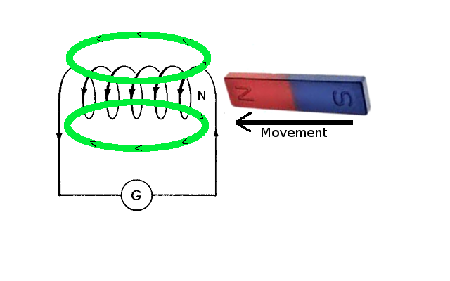
From previous topics we know if a wire is coiled it acquires some magnetic properties we call inductance.

We also know this inductance does not like change.

Apply a positive change (increase) to  coil and it absorbs it trying to stabilise or oppose the change.

Apply a negative change to a coil - and if was charged with any energy - it will release it into the circuit opposing the negative change.

This inducing energy into the circuit is called "self induced emf".

-----------------===========---------------

Inductance under DC supply.

As we said inductance only jumps into action when there is change in the supply. No change - no response from the inductor.

So a DC supply does not even know the coil exist but bring some change in that DC supply and the inductance is created.

The biggest change, for instance,  would be when we apply the DC and when we remove the DC supply.

If the supply does change (or when we just applied the supply) - the inductor will absorb that change - so as to say don't do this please!

But just like a tank has space (volume) - so does an inductor. When it is empty there is a lot of space and as it fills it "proportionally" gets smaller and it can take in less.

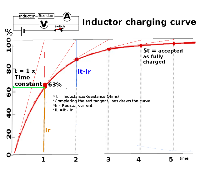
We can draw this phenomena over a time curve and refer to it as a charge curve.

But what happens when we remove the supply? 

Mr. Inductor is now full of charge and yet again it complains...why are you changing the supply and he releases his energy to try and compensate.

The curve over time looks identical to the charge curve and than its referred to  as the discharge curve.

By the way...the charge/discharge curve is so accurate and predictable that we design timers around it.

Drawing the charge/discharge curve we discover a characteristic referred to as the time constant.

What is the time constant: (this is so cool!)

Conventional knowledge says it is when 63% charged...no its not!

I was even taught at college this is the "linear section" of the graph. Its not.

At any time on the curve (graph = Current over time) there would be a current component spent on the emf (induction) and a component for the resistance of the circuit.

We always know Ir so IL must be = It-Ir: this gives us a relationship for a gradient as the inductance IL drops over time. 

In reality though - I through Ir = IL so the currents can cancel out leaving us with L/R.

This is the clever part...(disregard the fact that IL current at the next point would have decreased) and simply complete the gradient over the time at that point...it will complete a time period on the time axis. That is the time constant.

By repeating above procedure one can plot the charge curve.

Wow!

Practically speaking it is accepted at 5t inductor fully charged.


What if we wanted to really upset that inductor and put an ever changing waveform on it like a AC waveform?

For every change in the waveform the inductor will hit back with an opposite reaction by as much as its inductance (dependant on the number of turns in the coil) can muster. Read on an oscilloscope it is exactly opposite to the voltage applied waveform. That makes perfect sense.

This creates two voltages in the circuit at 180 Degrees apart, this causes the current to be stuck right between the two...at 90 Degrees behind the original waveform (voltage).

Guess what this reaction from the inductor is called....Inductive Reactance and it can be equated to be the resistance of the coil.

No one could have chosen a better word.

The obvious factors that will affect inductance is:

  1. How many turn the coil has i.o.w its inductance(L).
  2. Then how fast are we applying the change (rads/sec).

If we applied an AC wave form the the angular velocity is 2 * Pi * f [Frequency] (see angular velocity)

The formula would then be:

Inductive reactance (XL) = 2PiFL measured in Ohms.


Electrically we would not care much but the wrath of the inductor has only started...we will pay dearly one day ...quite literally.

But that's a story for another day...and its called power factor.


-----------------------------

CAPACITORS

Capacitors are components capable of storing electricity (charge).

Their construct is an insulator dielectric material between two different types of plates.

In the discharged state the metal plates are equally charged.

If a voltage (emf) is applied to the plates the charges are polarised.

One plate becomes only positively charged and the other only negative charged and because the dielectric is an insulator the capacitor maintains its charge.

As soon as the plates are connected via an external circuit the electrons will want to equalise this causing a current to flow for as long as there is a charge difference.

A nice surprise is the unit in which capacitance is measured: Farad (F)...and who is the father of "induction"...Mr. Faraday.

Maybe "Faraday" was too long to complete?


What is a Farad?

A farad is the capacitance that will store one coulomb of charge when one volt is applied across the plates of the capacitor.

 
Q = Voltage * Capacitance

Capacitance in an AC circuit.

A capacitor does not like change in the supply.

If the voltage changes it opposes the change by absorbing the voltage, thereby charging the capacitor. If the variance is negative w.r.t. to the capacitor and the capacitor has any charge in it, it will inject its energy into the circuit in order to maintaining a constant voltage.

This logic means the capacitance "response" is exactly 180 Degreesv(opposite) to whatever change in applied voltage.

What is the  original waveform? Whatever the waveform would have been with no capacitance in circuit.

Lets extrapolate the effects of capacitance by analysing the effects what happens the waveform of If at first we havb

A ggod method tho analyse the nature of capacitance in a circuit is to apply an AC sine wave supply and analyse the effects from the the generated waveforms.

  1. Step 1: The AC supply has the voltage and current in phase, in other words they run exactly concurrently. For reference lets call this the "original waveform".

  2. On connect the capacitor every positive change is opposed by the capacitor forming a waveform directly opposite to the original waveform i.e. 180 degrees.

  3. The result is at the original waveform positive peak the capacitors negative occur at the same time cancelling out the voltage and a new waveform which will be zero at this point is formed.

  4. As the original waveform descends from a peak decreasing and the capacitor - already charged with a negative charge - starts working together (remember the cap always responds oppositely)  creating a new waveform which increases toward a positive peak and at Vc and Vo = 0 the new waveform will peak.

  5. As the original waveform descends into the negative going towards its negative peak the capacitor is going positive increasing towards its positive peak and when they reach peak values...they cancel out...the new waveform reads 0 volts.

  6. bottom from a peak decreasing (going negative) and the the capacitor - already charged with a negative charge - starts working together creating a new waveform which increases toward a positive peak and at Vc and Vo = 0 the new waveform will peak, and so the waveform completes itself approaching 0/360Degrees.

In a nutshell: Because the capacitor fights against the voltage it causes it to lag the original waveform - which is what the current still follows, meaning the voltage lags the current by 90 degrees...smack in the middle of the two opposing voltages.  


Capacitive:

Capacitors connected in parallel increases the plate area across the supply therefore increases the capacitance.

Capacitors in series has the effect of increasing the dielectric thereby decreasing the capacitance in the circuit. 

Capacitance values calculates exactly the opposite (inverse) of resistive circuits.

Connection Resistors Capacitance
Parallel: 1/Rt = 1/R1 + 1/R2 +1/Rn Ct = C1+C2+Cn
Series Rt = R1 + R2 + Rn 1/Ct=1/C1 + 1/C2 +1/Cn
     

-----------


Time constant RC = T = Resistance(Ohms) * Capacitance(Farad)

A cap is considered fully charged after the 5th TC.

----------------================------------

Looking at the graph it is clear that the capacitance fights against a changing voltage thus causing it to only max out much later. This has a real effect on the circuit with the voltage lagging the current.

-----------=============---------

Energy stored in a cap = 1/2CV2 joules,


SEE HERE FOR THE COMPLETE POST / TOPIC LIST.


References: Thank you to the following who unwittingly or wittingly collaborated to build knowledge. For any infringements, apologies. Let us know here:

Copyright issues