|


| |
|
Circuit breakers |
|
Definition:
Circuit breaker:- A manually (or remote) operated device capable of making, current-carrying and breaking
currents under normal circuit conditions and also automatically breaks a
circuit under specified abnormal
conditions such as overload and short circuit currents
 Definition:
Circuit breaker:- A mechanical switching device capable of
protecting the circuit wiring, capable of making, carrying and breaking
currents under normal circuit conditions and also making, carrying for a
specified time and breaking currents under specified abnormal circuit
conditions such as those of short circuit (IEC 947-1).
|
|
Acronyms:
| SCPD |
Short-Circuit Protective Device |
| CB |
|
| MCB |
Miniature circuit breaker - 0.5 o 125Amp, |
| MCCB |
A circuit breaker having a supporting housing of moulded
insulating material forming an
integral part of the circuit breaker (IEC 947-2). |
| ACB |
Air circuit breaker |
|
|
| In depth look at the
tripping curve:

---------===========---------

Figure
4 – Ground-fault Characteristic Curve
-----------==========-------- |
|
|
Definitions and explanations:
In= Nominal trip current indicated on CB.
|
|
Interrupting
short-circuit current:-
As an example, let us consider a quick acting, current limiting circuit
breaker a
described previously.
To limit the short-circuit current already at its initiation, the main
contacts must
be opened by the striker within a few milliseconds. A very fast acting
device
may need less than 1ms for this. An arc is struck immediately, which driven
towards the arc chamber, delivers a high arc voltage. As a simplification,
the ar
voltage can be considered as an equivalent additional resistance connected
in
series to the current circuit which immediately limits the rising
short-circuit
current.
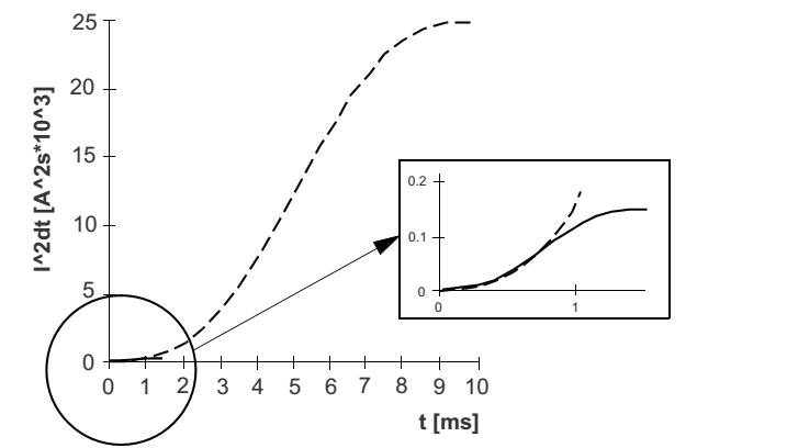
Let-through energy (Joule integral)
of the fast acting circuit breaker 140M
The energy of the short-circuit current integrated over a time period, also
called
the let-through energy I2t (Joule integral), indicates how the components
installed downstream of the circuit breaker, especially switching devices
like a contactor, are less stressed when protected by a current limiting
circuit breaker instead of a current-zero interrupting type.
Note : Although popularly called the let-through energy, the
Joule-Integral gives
only an indication of the let-through energy and do not have the dimension
of
energy. The Joule-Integral multiplied the resistance of the current path is
actu
ally the let-through energy.
The resulting low let-through values of the current limiting circuit
breaker cause
no or very little damage to the components or devices installed downstream
of
the circuit breaker. With the right choice of the various components,
strongly
welded contacts of contactors or severe damage to the connecting wiring or
bus
bars due to uncontrolled arcing can be prevented.
---------------=============------------- Motor protection circuit
breakers:- Adjustable, current dependant
time-delayed overcurrent release protects against thermal overloading.
The ambient air temperature compensation and a precise calibration of the
overcurrent release mechanism assures an exact and reliable tripping. Often
a differential release for the protection against the loss of a phase is
integrated in the device. After the interruption of a short-circuit, the
tripping characteristic must not alter without any outwardly visible
indication. 
Fig. 1.4-3: Tripping
curve of a circuit breaker with motor protective characteristics. The
grey line indicates the current form of a normal motor. After the rated
speed is reached (here after about 1.5s), the starting current (6 x In)
reduces to the rated current of the motor(1xIn).
a) Time-current characteristic of the bimetallic release
b) Time-current characteristic of the magnetic release
c) Characteristic of the motor |
|
|
Current limiting circuit breaker
Interrupting
short-circuit current:-
As an example, let us consider a quick acting, current limiting circuit
breaker a
described previously.
To limit the short-circuit current already at its initiation, the main
contacts must
be opened by the striker within a few milliseconds. A very fast acting
device
may need less than 1ms for this. An arc is struck immediately, which driven
towards the arc chamber, delivers a high arc voltage. As a simplification,
the arc
voltage can be considered as an equivalent additional resistance connected
in
series to the current circuit which immediately limits the rising
short-circuit
current.
Let-through energy (Joule integral)
of the fast acting circuit breaker 140M
The energy of the short-circuit current integrated over a time period, also
called
the let-through energy I2t (Joule integral), indicates how the components
installed downstream of the circuit breaker, especially switching devices
like a contactor, are less stressed when protected by a current limiting
circuit breaker instead of a current-zero interrupting type.
Note : Although popularly called the let-through energy, the
Joule-Integral gives
only an indication of the let-through energy and do not have the dimension
of
energy. The Joule-Integral multiplied the resistance of the current path is
actually the let-through energy.
The resulting low let-through values of the current limiting circuit
breaker cause
no or very little damage to the components or devices installed downstream
of
the circuit breaker. With the right choice of the various components,
strongly
welded contacts of contactors or severe damage to the connecting wiring or
bus
bars due to uncontrolled arcing can be prevented. |
Other special characteristics circuit breakers:
- Current-zero interrupting type:-
- Current limiting type:-Interrupt the current during the
initiation of the short-circuit, before the full prospective value can be
attained.
1.2.2.2. Current-zero interrupting type of circuit breaker (“Basics of Circuit breakers - thanks to : http://electrical-engineering-portal.com/download-center/electrical-software/selection-of-mccb-elcb-for-main-branch-circuit 1.2.2.3. Special features of the current limiting circuit breaker In order to reduce the mechanical (due to electro-dynamic forces) and thermal stresses on the object to be protected, the current must be interrupted right during the initiation of the short-circuit, before the full prospective value can be attained (as for example to avoid the welding of the contactor contacts). This is achieved by : • Quick opening of the main contacts. • Rapid build-up of a high arc-voltage (move the arc quickly away from the contact tips and guide it to the arc chamber). The effects of the reduced let-through values are : • Reduction of the electro-dynamic forces on the bus-bars (as for example increased spacing between supports). • Reduction of thermal stresses. The welding of the contacts of contactors can be prevented. Over-dimensioning of the contactors can be avoided or at least kept within reasons. The result is reflected in the short-circuit co-ordination tables - compact starter combinations with components selected mostly on the basis of their rated currents. The current limiting circuit breakers are used in a wide field of applications. It is no longer necessary to carry out complex calculations of the short-circuit current at each point of the network where a circuit breaker is installed. The subject of short-circuit co-ordination takes about as much planning effort as in the case of fuses. The circuit breaker should be constructed in such a way that it can interrupt the short-circuit current under all possible situations without any problem whatsoever. The features, which make the planning with circuit breakers as simple as that with fuses, are : • High breaking capacity makes calculation of short-circuit current superflu- ous: in actual applications, the fault level (prospective short-circuit current) at the point where circuit breakers for motor branch circuits are installed lie mostly in the range of 1…20kA. If the breaking capacity of the circuit breaker is higher than this, no further calculation is necessary. The circuit breakers can be utilised in any point of the installation without calculations for its dimensioning, similar to a high rupturing capacity fuse. • Low let-through values: the contactors connected downstream are less stressed as the short circuit current is appreciably limited by the circuit breakers. Short-circuit co-ordination is simplified and it is not necessary to consult the short-circuit co-ordination tables (the manufacturers perform tests for the short-circuit co-ordination and supply tables in accordance with the IEC 947-4-1 for, as for example, types "1" or "2"). The combination of a circuit breaker and a contactor, both selected on the basis of their rated cur- rents, can in most of the cases fulfil the requirements of the type of co-ordi- nation "2", without any other considerations.
|
|
1.2.2.2. Current-zero interrupting
type of circuit breaker (“Basics of Circuit breakers -
thanks to :
http://electrical-engineering-portal.com/download-center/electrical-software/selection-of-mccb-elcb-for-main-branch-circuit
1.2.2.3. Special features of
the current limiting circuit breaker
In order to reduce the
mechanical (due to electro-dynamic forces) and thermal
stresses on the object to be
protected, the current must be interrupted right during
the initiation of the
short-circuit, before the full prospective value can be attained
(as for example to avoid the
welding of the contactor contacts).
This is achieved by :
•
Quick opening of the main
contacts.
•
Rapid build-up of a high
arc-voltage (move the arc quickly away from the
contact tips and guide it to
the arc chamber).
The effects of the reduced
let-through values are :
•
Reduction of the
electro-dynamic forces on the bus-bars (as for example
increased spacing between
supports).
•
Reduction of thermal stresses.
The welding of the contacts of contactors can
be prevented. Over-dimensioning
of the contactors can be avoided or at least
kept within reasons. The result
is reflected in the short-circuit co-ordination
tables - compact starter
combinations with components selected mostly on
the basis of their rated
currents.
The current limiting circuit
breakers are used in a wide field of applications. It is
no longer necessary to carry
out complex calculations of the short-circuit current
at each point of the network
where a circuit breaker is installed. The subject of
short-circuit co-ordination
takes about as much planning effort as in the case of
fuses.
The circuit breaker should be
constructed in such a way that it can interrupt the
short-circuit current under all
possible situations without any problem whatsoever.
The features, which make the
planning with circuit breakers as simple as that
with fuses, are :
•
High breaking capacity makes
calculation of short-circuit current superflu-
ous: in actual applications,
the fault level (prospective short-circuit current)
at the point where circuit
breakers for motor branch circuits are installed lie
mostly in the range of 1…20kA.
If the breaking capacity of the circuit
breaker is higher than this, no
further calculation is necessary. The circuit
breakers can be utilised in any
point of the installation without calculations
for its dimensioning, similar
to a high rupturing capacity fuse.
•
Low let-through values: the
contactors connected downstream are less
stressed as the short circuit
current is appreciably limited by the circuit
breakers. Short-circuit
co-ordination is simplified and it is not necessary to
consult the short-circuit
co-ordination tables (the manufacturers perform
tests for the short-circuit
co-ordination and supply tables in accordance with
the IEC 947-4-1 for, as for
example, types "1" or "2"). The combination of a
circuit breaker and a
contactor, both selected on the basis of their rated cur-
rents, can in most of the cases
fulfil the requirements of the type of co-ordi-
nation "2", without any other
considerations.
-----------===========-----------
|
| |
|
Types:
Thermal and or magnetic:
Hydraulic magnetic:
|
| |
|
|
Tripping curves:
Other special characteristics circuit breakers:
- Current-zero interrupting type:-
- Current limiting type:-Interrupt the current during the
initiation of the short-circuit, before the full prospective value can be
attained.
|
|
|
Summary: circuit breaker as load break switch
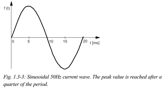
Analysis of a short circuit:-
The short-circuit current reaches its peak value
after a quarter of the sinusoidal period, which is 5 milliseconds for 50Hz
supply (4.2ms in the case of 60Hz as in the USA), assuming that the current is
symmetrical, i.e. initiated at a current zero. This is to be prevented.
|
|
|
|
|
| |
|
How shall a circuit
breaker be rated:
| SANS.5.2 |
NEC |
SANS |
|
|
| |
|
|
|
|
|
|
An interesting note I found in NEC article 100 definitions: was that the automatic means does
not have to be an integral part of the circuit breaker - that is a
surprise.gs |
For a circuit breaker it must, at a specific voltage
(considering the circuit power factor) and the fault current
equalling its rated breaking capacity or lower be capable of breaking
the circuit. gs
Strange we don't find the "make" anywhere? gs
5.1.3 - EFP
5.2.5 - protection
equipment
7.13 hiV apparatus
2.2.1 South African standards
SANS 152 (SABS 152), Low-voltage air-break switches, air-break
disconnectors, air-break switch-disconnectors
SANS 156 (SABS 156), Moulded-case circuit-breakers.
SANS 556-1, Low-voltage switchgear – Part 1: Circuit-breakers.
SANS 767-1 (SABS 767-1), Earth leakage protection units – Part 1: Fixed
earth leakage protection circuit-breakers.
SANS 61008-1/IEC 61008-1, Residual current operated circuit-breakers
without integral overcurrent protection for household and similar uses (RCCBs)
– Part 1: General rules.
UL 508, Industrial control equipment. check his out in SANS 3.71
short-circuit protective device
SCPD device intended to protect a circuit or p
A
|
|
|
|
How is it
selected for overload current protection
| SANS10142: 6.7.x |
IEC 60364 |
NEC Article 230.42 |
|
6.7 Protection
6.7.1 Overcurrent protection
NOTE The term over current protection includes both overload protection
(see 6.7.2) and short-circuit protection (see 6.7.3).
6.7.1.1
Each protective device shall have a rated current that does not exceed
the lowest of the current-carrying
capacities of any of the conductors of the circuit and shall have a
minimum short-circuit rating of 2,5 kA.
6.7.2 Overload protection
6.7.2.1
Overload protection:
The rated current of the overload protective device shall not
exceed the current-carrying capacity of the conductor it protects,
except in the case of circuits in which the presence of overload
protection could create a dangerous situation, such as in circuits for
lifting magnets
BTW: No mention of the component current
ratings?gs
|
4.4.4.1
Reference:- ABB Comparison of
tripping characteristics
for miniature circuit-breakers
For protection against overload, the
protective device must be selected based on the current carrying
capacity
Ib
≤
In ≤
Iz (standard)
Idesign
≤
Icb ≤
Icable (mine)
and
I2
≤
1.45 x Iz (standard)
Ioperation
≤
1.45 x Icable (mine)
Ib= Design current of a circuit
In= Rated current of the protective
device
Iz= Current carrying capacity of the
cable in accordance with IEC/HD 60364-5-52
I2 = Current ensuring effective
operation in the conventional time of the protective device
IEC 60364-4-43h
|
Where a feeder supplies continuous loads or any combination of
continuous and noncontinuous loads, the rating of the
overcurrent device shall not be less than the noncontinuous load plus
125% of the continuous load.
Exception: Where the assembly including the overcurrent
devices protecting the feeder(s) are
listed for operation at 100% of their rating, neither the ampere rating
of the overcurrent device nor the ampacity of the feeder conductors
shall be less than the sum of the continuous load plus the noncontinuous
load.
Only breakers listed for 100% application,
and so labelled can be applied under the exception (for example loads
Frame and R Frame 140G’s that are specifically marked and rated 100%).
Breakers without a 100% application listing and label are
applied at 80% of rating
I could not find this in the NEC 2011
this is in 2011:II. Branch-Circuit Ratings
210.19 Conductors — Minimum Ampacity and Size.
(A) Branch Circuits Not More Than 600 Volts.
(1) General. Branch-circuit conductors shall have an ampacity not less
than the maximum load to be served. Where a branch circuit supplies
continuous loads or any combination of continuous and noncontinuous
loads, the minimum branch-circuit conductor size, before the application
of any adjustment or correction factors, shall have an allowable
ampacity not less than the noncontinuous load plus 125 percent of the
continuous load.
Exception: If the assembly, including the overcurrent devices protecting
the branch circuit(s),
is listed for operation at 100 percent of its
rating, the allowable ampacity of the branch circuit conductors
shall be permitted to be not less than the sum of the continuous load
plus the noncontinuous load.
Informational Note No. 1: See 310.15 for ampacity
ratings
of conductors.
Informational Note No. 2: See Part II of Article 430 for
minimum rating of motor branch-circuit conductors.
Informational Note No. 3: See 310.15(A)(3) for temperature limitation of
conductors. |
|
b) Opening under overload conditions
1) Instantaneous or definite time-delay operation
The release shall cause tripping of the circuit-breaker with
an accuracy of i10 O/. of the tripping current value of the current setting
for all values of current setting of the overload
release.
2) Inverse time-delay operation. Conventional values for
inverse time-delay operation are given in table 6.
|
IEC 60947-2:
7.2.5 Ability to make and break under short-circuit
conditions
Subclause 7.2.5 of Part 1 applies with the following
amplifications:
The rated short-circuit making capacity shall be in
accordance with 4.3.5.1(Rated short circuit making capacity) and
4.3.5.3 (Standard relationship between short-circuit making and breaking
capacities and related power factor, for a.c. circuit-breakers)
The rated short-circuit breaking capacity shall be in
accordance with 4.3.5.2
The rated short-time withstand current shall be in
accordance with 4.3.5.4
NOTE It is the manufacturer’s responsibility to ensure that
the tripping characteristic of the circuit-breaker IS compatible with the capability of the circuit-breaker to withstand the
inherent thermal and electrodynamlc stresses
---============-----
and the association shall comply with the requirements of 7.2.1.2.4, item
a)
-----===========----
7.2.1 .2.4 Opening by over-current releases a)
b)
Opening under short-circuit conditions
The short-circuit release shall cause tripping of the
circuit-breaker with an accuracy of
20% of the tripping current value of the current
setting for all values of the current setting
of the short-circuit current release.
Where necessary for over-current co-ordination (see
2.17), the manufacturer shall provide Information (usually curves)
showing. maximum cut-off (let-through) peak current (see 2.5 19 of Part
1) as a function of prospective current (r, m.s. symmetrical);
— /2t characteristics (see 2.18) for circuit-breakers of
utilization category A and, if applicable, B for circuit-breakers with
instantaneous override (see note to 8.3.5).
Conformity with this information may be checked during
the relevant type tests in test
sequences II and Ill (see 8.3.4 and
8.3.5).
NOTE It may be possible to provide other forms of data
to verify co-ordination characteristics of circuitbreakers, for example,
tests on combinations of short-circuit protective devices.
Opening under overload conditions
1) Instantaneous or definite time-delay operation
The release shall cause tripping of the circuit-breaker
with an accuracy of i10 O/. of
the
tripping current value of the current setting for all
values of current setting of the overload release.
2) Inverse time-delay operation Conventional values for
inverse time-delay operation are given in table 6.
At the reference temperature (see 4.7.3) and at 1,05
times the current setting (see 2.4.37
of Part 1), i.e. with the conventional non-tripping
current (see 2.5.30 of Part 1), the opening
release being energized on all phase poles, tripping
shall not occur in less than the
conventional time (see 2.5.30 of Part 1) from the cold
state, i.e. with the circuit-breaker at the reference temperature.
Moreover, when at the end of the conventional time the
value of current is immediately raised to 1,30 times the current
setting, i.e. with the conventional tripping current (see 2.5.31 of Part
1), tripping shall then occur in less than the conventional time later.
NOTE The reference temperature is the ambient air
temperature on which the time-current characteristic of the
circuit-breaker is based. 4.7.3
Table 6
simply says
for
lower/equal to 63Amps - at 1.05In circuit must trip after 1 hr only, if
then raised to 1.3In it must trip ONLY within 1hr
at bigger
then 63amps it becomes 2hr
They talk
about this time as conventional time. |
|
| |
DEFINING THE TRIPPING CURVE
4.7.4 Tripping time
setting of over-current releases
1) Definite time-delay over-current releases
The time-delay of such releases is independent of the over-current.
The
tripping time setting shall be stated as the duration in seconds of the
opening time of the circuit-breaker, if the time-delay is not
adjustable, or the extreme values of the opening time~ if the time delay
is adjustable.
2) Inverse time-delay over-current releases
The time-delay of such releases is dependent on the over-current.
The time/current characteristics shall be given in the form of curves
supplied by the
manufacturer.
These shall indicate how the opening time, starting from
the cold state, varies with current within the range of operation of the
release.
The manufacturer shall indicate, by suitable means,
the tolerances applicable to these curves.
These curves shall be given for each extreme value of
the current setting and, if the time
setting for a given current setting is adjustable, it is recommended
that they be given in
addition for each extreme value of the time setting.
NOTE It is recommended that the current be plotted as
abscissa and the time as ordinate, using logarithmic scales.
Furthermore, in order to facilitate the study of
co-ordination of different types of over-current protection,
!t is
recommended that the current be plotted as multiples of the setting
current and the time in seconds on the standard graph sheets detailed in
5.6.1 of IEC 60269-1 and in figures 4(l), 3(11) and 4(11) of IEC
60269-2-1. |
|
| |
Circuit breaker
Reference temperature: lS/lEC 60947-2:2003
Unless otherwise specified – the operating value of
overload releases other than those of the thermal type is independent of
the ambient air temperature within the limits of -5 “C to +40 ‘C;
for releases of the thermal type, the values stated are
for a reference temperature of +30 “C i 2 “C. The manufacturer shall be
prepared to state the influence of variations in the ambient air
temperature (see 7.2.1.2.4, item b)).
|
|
| |
|
|
And short circuit currents:
| SANS10142: 6.7.3 |
|
|
Short-circuit protection
6.7.3.1 At its point of installation, a short-circuit protective device
shall be capable of breaking any over current up to the value of the
prospective short-circuit current. (See also 6.7.4 on cascaded systems.)
|
|
|
|
| And the impedance?
| BS EN 60947-2 - calculating Zs |
|
|
In this case Zs is determined from the basic equation:-
Zs Ia≤ UoCmin– which transposes to: - Zs≤ ((UoCmin)/Ia) where:-
Uo is the nominal voltage to earth.
Ia is the current required to achieve the disconnection time as given in
the Regulations.
Cmin is the minimum voltage factor to take account of voltage
variations depending on time and place, changing of transformer taps and
other considerations.
NOTE: For a low voltage supply given in accordance with the
Electricity Safety, Quality and Continuity. Regulations 2002 as amended,
Cmin is given the value 0.95.
|
|
|
|
| |
| |
|
|
|
|
What does the
standards say about Prospective fault current?
| SANS 10142 |
IEC |
|
6.6.1.15 Switchgear shall be fully rated
for withstanding the prospective
short-circuit current that could occur at that point in the system,
unless
series-connected (cascaded)
systems are applied in accordance with
6.7.4.6.6.1.16 Where the prospective fault
level of the supply cannot be determined, a fault current meter may be
used (see 8.5.2).
6.6.1.17 All
disconnecting devices in a distribution board
a) shall be protected by a fully rated short-circuit protective device,
and
b) when used in combination with a short-circuit protective device (see
6.7.4), shall have a conditional
short-circuit current rating (see 3.22.1)
appropriate to its condition of installation, but of not less than 2,5
kA
|
|
|
|
|
|
|
|
| |
|
|
|
|
| |
|
|
|
|
| |
| |
IEC 60947.2: 4.4: Utilisation categories |
|
| |
Table 4- Utilization categories
Category ACircuit-breakers not
specifically intended for selectivity under short-circuit conditions with respect to other short-circuit
protective devices in series on the load side, i.e. without an intentional
short-time delay provided for selectivity under short-circuit conditions,
and therefore without a short-time withstand current rating according to 4.3.5.4.
Category B
Circuit-breakers specifically intended for selectivity
under short-circuit conditions with respect to other short-circuit
protective devices in series on the load side, i.e. with an intentional short-time
delay (which may be B adjustable), provided for selectivity under
short-circuit conditions. Such circuit-breakers have a short-time withstand current
rating according to 4.3.5.4.
NOTE Selectivity is not necessarily ensured up to the
ultimate shortcircuit breaking capacity of the circuit-breakers (for example
in the case of operation of an instantaneous release) but at least up to the
value specified in table 3.
table 11 (see 8.3.2.2.4 and 8,3.2,2.5),
NOTE 2 Attention is drawn to the different requirements
for the minimum required percentage of lc~ for utilization categories A and B, in accordance with table
1.
NOTE 3 A circuit-breaker of utilization category A may
have an intentional short-time delay provided for selectivity under conditions other than those of short
circuit, with a short-time withstand current less than that according to table 3. In that case, the tests include test sequence
IV (see 8.3.6) at the assigned short-time
|
|
|
| Hager |
|
|
| •Ref:Electricians handbook courtesy of
Larson and Toubro - India:
IEC classifies MCBs into three category depending upon their “Quality
of current
limiting” & let through energy of a circuit breaker on short circuits.
Permissible let to energy values for circuit breakers with rated current
up to end including 16A as per
EN60898 are:
Class 1 No limitation
Class 2 290 kA²S
Class 3 84 kA²S -
*All Hager mcb are class 3
|
|
|
|
|
Where must it be installed?
| south Africa
SANS10142: 6.7.1.1 |
Europe + IEC 60364
|
USA+ UL489
UL1077
|
Canada
CSA c22.2 No 5.02CSA c22.2 No 235-04
|
|
china GB 14048-2 |
| 6.7.2.2 Overload must be installed at point of conductor
reduction OR - with a switch/disconnector OR earth-leakage unit that
requires overload protection. UNLESS
The over current device can sit anywhere in the cable as long as no
connections to/from it
AND
entire length protected against shorts circuit OR
cable shorter then 5mtrs
not near flammable materials
not likely to cause humans harm
I spent a lot of time trying to get
to grips with this - I get this feeling this commission could not get
consensus the matter of "anywhere in the cable"...thus the strange
additions. Flammable and human safety? Really?
Now the challenge: Overload unit
can be anywhere in the cable but the whole cable must be short circuit
protected? HOW?
Mechanical protection or another
electrical component? Are
we confusing motor overload protection with cable / reticulation
protection here? |
G-2 CASES WHERE SHORT-CIRCUIT PROTECTION DOES NOT
NEED TO BE PLACED AT THE ORIGIN OF BRANCH CIRCUIT With
reference to 4.4.5.2.1and Fig. G.1, short-circuit protective device P
2may be moved up to 3 m from the origin (O) of the branch circuit (S2)
provided that there is no other connection or socket-outlet on this
length of the branch circuit, and in the case of 4.4.5.2.1
the risk of short-circuit, fire and danger to persons is reduced to a
minimum for this length.
but:
4.4.4.2 Position of devices for overload protection
4.4.4.2.1 A device ensuring protection against overload shall be placed
at the point where a
change, such as a change in cross-sectional area, nature, method of
installation or in constitution,
causes a reduction in the value of current-carrying capacity of the
conductors, except where
4.4.3.2.2and 4.4.3.3 apply.
4.4.4.2.2 The device protecting the conductor against
overload may be placed along the run of that conductor if the part of
the run between the point where a change occurs (in cross-sectional
area, nature, method of installation or constitution) and the position
of the protective device has neither branch circuits nor socket-outlet
circuits and fulfils at least one of the following two conditions:
a) it is protected against short-circuit current in accordance with the
requirements stated in 4.4.5;
b) its length does not exceed 3 m, it is carried out
in such a manner as to reduce the risk of shortcircuit to
a minimum, and it is installed in such a manner as to reduce to a
minimum the risk of
fire or danger to persons (see also 4.4.5.2.1).
NOTE: For installation according to a) see Figure F.1.
For installation according to b) see Figure F.2. |
|
|
|
|
| |
|
|
|
|
|
| 6.7.2.3The overload protective device
may be installed at any point in the conductor run that it protects,
provided that
a) there is no branch circuit or socket-outlet between
the point where there is a reduction in the conductor's current-carrying
capacity and the point where the device is installed, and
b) the entire length of the conductor is protected against
short-circuit, or
c) the conductor is
1) of length not exceeding 5 m,
2) so installed as to minimize the risk of overload or fault in its
operating condition,
3) not near flammable materials, and
4) not likely to cause harm to a person in the event of a fault |
|
|
|
|
|
| Now short circuit protection is as plain
and simple as "installed at the point of reduction" - as it should be!
6.7.3.2 |
AND SHORT CIRCUITS?
4.4.5.2 Position of devices for short-circuit
protection A device ensuring protection against short-circuit shall
be placed at the point where a reduction in the cross-sectional area of
the conductors or another change causes a change to the current-carrying
capacity of the conductors, except where 4.4.5.2.1, 4.4.5.2.2or 4.4.5.3
applies.
4.4.5.2.1 The various cases stated in the following sub clause shall not
be applied to installations situated in locations presenting a fire risk
or risk of explosion and where special rules for certain
locations specify different conditions. The device for protection
against short-circuit may be placed other than as specified in 4.4.4.2,
under the following conditions.
In the part of the conductor between the point of
reduction of cross-sectional area or other change and the position of
the protective device there shall be no branch circuits nor
socket-outlet circuits
and that part of the conductor shall:
a) not exceed 3 m in length, and
b) be installed in such a manner as to reduce the risk of a
short-circuit to a minimum,
and so forth and so forth...
|
|
|
|
|
|
|
... |
| |
|
Omitting fault current protection device
| IEC 60364 |
|
4.4.4.3 Omission of devices for
protection against overload
The various cases stated in this sub-clause shall not be applied to
installations situated in locations
presenting a fire risk or risk of explosion or where the requirements
for special installations and
locations specify different conditions.
4.4.4.3.1 General Devices for protection against
overload need not be provided:
a) for a conductor situated on the load side of a change in
cross-sectional area, nature, method of
installation or in constitution, that is effectively protected against
overload by a protective
device placed on the supply side;
b) for a conductor that is not likely to carry overload current,
provided that this conductor is
protected against short-circuit in accordance with the requirements of
4.4.4 and that it has neither branch circuits nor socket-outlets;
c) at the origin of an installation where the distributor provides an
overload device and agrees that it affords protection to the part of the
installation between the origin an d the main distribution point of the
installation where further overload protection is provided.
d) for circuits for telecommunications, control, signalling and the
like.
NOTE: For installations according to a), b) and d), see Fig. F.3.
|
|
| |
|
| |
|
|
|
Relevant standards and circuit breakers:
PS: This is a reference based on manufacturer material
referring to the different standards - Excuse if you are specialist and find
some discrepancy...just let us know - for this is always a work in progress
we would be a happy to oblige.
| |
UL |
ANSI |
NEC |
CSA |
IEC |
| Genl |
|
|
Articles: 210 - Branch circuits
215 - Feeders
240 - Overcurrent Protection
430 - Motors, Motor Circuits, and Controllers
controllers, and m |
|
|
| MCB |
UL1066 - LV AC and DC CB in Enclosures
|
- ANSI C37.13: IEEE Standard for Low-Voltage AC Power
Circuit Breakers Used in Enclosures
- ANSI C37.16: Low-Voltage Power Circuit Breakers and AC
Power Circuit Protectors.
Preferred Ratings, Related Requirements, and Application
Recommendations
- ANSI C37.17: American National Standard for Trip
Devices for AC and General
Purpose DC Low Voltage Power Circuit Breakers
|
|
|
IEC 60947-2 (circuit breaker design and manufacturing)
IEC 60364, § 434.5.1 (electrical distribution network).
 | IEC 947-4 - Circuit breakers with motor
protective characteristics. |
|
| MCCB |
UL 489 - NEC -Branch circuit protection. MCCB. UL 489: Molded-Case
Circuit Breakers, Molded-Case Switches and Circuit
Breaker Enclosures
UL 489 MCCB: MCS(Molded Case Switches) & Circuit Breaker Enclosures.
| UL 489A - Branch circuit protection DC circuit breaker short circuit
protection in communications equipment. |
| UL1077 - Used in conjunction with CB for supplementary external device
protection. |
| Branch circuit protection. |
| UL1077 - Used in conjunction with CB for supplementary external device
protection. |
| |
| UL486- evaluation of lugs connection in field wiring this includes
items under UL489. |
| |
|
|
|
CSA C22.2 No. 5. 5-02 - CEC - Canadian -
CSA C22.2 No.235 - Used in conjunction with CB for supplementary
external device protection. |
|
| ACB |
|
|
|
|
|
|
| |
| |
| |
| Definitions:
|
| |
|
Analysis of a short circuit:-
The short-circuit current reaches its peak value
after a quarter of the sinusoidal period, which is 5 milliseconds for 50Hz
supply (4.2ms in the case of 60Hz as in the USA), assuming that the current is
symmetrical, i.e. initiated at a current zero. This is to be prevented.
bxc |
Coordination/Cascading/Backup protection
And lets dig deeper according to what standards say:
| |
IEC 60947-2.2003
|
|
|
|
| |
he obvious is that the information all provided by
manufacturer and the components comply to relevant standards.
Ultimately: The maximum
conditional short-circuit current (see 2.5.29 of Part 1) shall not
exceed the rated ultimate short-circuit breaking capacity of the SC PD.
IEC 60947.2.2003
A.5 Verification of discrimination
Discrimination can normally be considered by desk study alone, i.e. by
a comparison of the
operating characteristics of C1 and the associated SCPD, for example, when
the associated
SCPD is a circuit-breaker (C2) provided with an intentional time-delay,
The manufacturers of both the C1 and the SCPD shall provide adequate data
concerning the
relevant operating characteristics so as to permit Is to be determined for
each individual
association.
In certain cases, tests at Is are necessary on the association, for
example
— when C1 is of the current-limiting type and C2 is not provided with an
intentional time-delay;
— when the opening time of the SCPD is less than that corresponding to one
half-cycle,
To obtain the desired discrimination when the associated SCPD is a
circuit-breaker, an
intentional short-time delay may be necessary for C2.
Discrimination may be partial (see figure A.4) or total up to the rated
short-circuit breaking
capacity Icu (or Ics) of C1. For total discrimination, the non-tripping
characteristic of C2 or
the pre-arcing characteristic of the fuse shall lie above the tripping
(break-time) characteristic
of C1.
Two illustrations of total discrimination are given in figures A.2 and A.3.
A.6 Verification of back-up protection
A.6.1 Determination of the take-over current: -Compliance with the
requirements of A.3,2 can be checked by comparing the operating
characteristics of Cl and the associated SCPD for ail settings of Cl and, if
applicable, for all
settings of C2.
A.6.2 Verification of back-up protection
a) Verification by tests.
Compliance with the requirements of A.3.3 is normally verified by tests in
accordance with
A.6.3. In this case, all the conditions for the tests shall be as specified
in 8.3.2.6 with the
adjustable resistors and inductors for the short-circuit tests on the supply
side of the
association.
b) Verification by comparison of characteristics
In some practical cases and where the SCPD is a circuit-breaker (see figures
A,4 and A.5),
it may be possible to compare the operating characteristics of Cl and of the
associated
SCPD, special attention being paid to the following:
– the Joule integral value of C1 at its Icu and that of the SCPD at the
prospective current
of association;
– the effects on C1 (e.g. by arc energy, by maximum peak current, cut-off
current) at the
peak operating current of the SCPD.
In some practical cases and where the SCPD is a circuit-breaker (see
figures A,4 and A.5),
it may be possible to compare the operating characteristics of Cl and of the
associated
SCPD, special attention being paid to the following:
– the Joule integral value of Cl at its /CU and that of the SCPD at the
prospective current
of association;
– the effects on Cl (e.g. by arc energy, by maximum peak current, cut-off
current) at the
peak operating current of the SCPD.
The suitability of the association may be evaluated by considering the
maximum total
operating I2t characteristic of the SCPD, over the range from the rated
short-circuit breaking
capacity Icu(or Ics) of C1 up to the prospective short-circuit current of
the application, but not
exceeding the maximum let-through I2t of C1 at its rated short-circuit
breaking capacity or
other lower limiting value stated by the manufacturer.
NOTE Where the associated SCPD is a fuse, the validity of the desk study is
limited up to Icu of
A.6.3 Tests for verification of back-up protection
If C1 is fitted with adjustable over-current opening releases, the operating
characteristics shall
be those corresponding to the minimum time and current settings,
If C1 can be fitted with instantaneous over-current opening releases, the
operating
characteristics to be used shall be those corresponding to Cl fitted with
such releases,
If the associated SCPD is a circuit-breaker (C2) fitted with adjustable
over-current opening
releases, the operating characteristics to be used shall be those
corresponding to the
maximum time and current settings.
If the associated SCPD consists of a set of fuses, each test shall be made
using a new set of
fuses, even if some of the fuses used during a previous test have not blown
Where applicable, the connecting cables shall be included as specified in
8.3.2.6.4 except that,
if the associated SCPD is a circuit-breaker (C2), the full length of cable
(75 cm) associated with
this circuit-breaker may be on the supply side (see figure A.6).
Each test shall consist of a O–t–CO sequence of operations made in
accordance with 8.3.5 of
this standard, ‘whether at /Cu or /C~, the CO operation being made on Cl.
A test is made with the maximum prospective current for the proposed
application, This shall
not exceed the rated conditional short-circuit (see 4.3.6.4 of Part 1),
A further test shall be made at a value of prospective current equal to
the rated short-circuit
breaking capacity /Cu (or /CS) of Cl, for which test a new sample Cl may be
used, and also, if
the associated SCPD is a circuit-breaker, a new sample C2.
a) if the associated SCPD is a circuit-breaker (C2):
– either both Cl and C2 shall trip at both test currents, no further tests
then being
required.
This is the general case and provides back-up protection only.
– or C1 shall trip and C2 shall be in the closed position at the end of each
operation, at
both test currents, no further tests then being required,
This requires that the contacts of C2 separate momentarily during each
operation. In this
case restoration of the supply is provided, in addition to back-up
protection (see note 1 to
figure A.4), The duration of interruption of supply, if any, shall be
recorded during these
tests.
– or C1 shall trip at the lower test current, and both C1 and C2 shall trip
at the higher test
current.
This requires that the contacts of C2 separate momentarily at the lower test
current.
Additional tests shall be made at intermediate currents to determine the
lowest current at
which both C1 and C2 trip, up to which current restoration of supply is
provided. The
duration of interruption of supply, if any, shall be recorded during these
tests.
– or C1 shall trip at the lower test current, and both C1 and C2 shall
trip at the higher test
current.
This requires that the contacts of C2 separate momentarily at the lower test
current.
Additional tests shall be made at intermediate currents to determine the
lowest current at
which both C1 and C2 trip, up to which current restoration of supply is
provided. The
duration of interruption of supply, if any, shall be recorded during these
tests.
b) if the associated SCPD is a fuse (or a set of fuses):
—
In the case of a single-phase circuit at least one fuse shall blow;
— in the case of a multi-phase circuit either two or more fuses shall blow,
or one fuse shall
blow and C1 shall trip.
A.6.4 Results to be obtained
Subclause 8.3.4.1.7 of Part 1 applies.
Following the tests, C1 shall comply with 8.3,5.3 and 8.3.5.4
In addition, if the associated SPCD is a circuit-breaker (C2), it shall be
verified, by manual
operation or other appropriate means, that the contacts of C2 have not
welded.
|
|
|
|
| |
|
|
|
|
...
|
|
Up side down circuit breakers
| SANS 2012 |
NEC |
|
|
6.8.2.3
Circuit-breakers, disconnectors and switch-disconnectors shall not be
mounted upside down.
Who would want to do this anyway...zimzum.
Horizontal mounting is
allowed unless specifically prohibited by the manufacturer.
Any deviation from the convention of connecting line to
the top and load to the bottom of switchgear is not recommended. Reverse
connection is allowed only if
a) it is specifically allowed by the manufacturer,
b) "load" and "line" are so marked that they are clearly
visible during
maintenance, and
c) any contradictory marking is not visible after
installation. |
NEC404.7
inferred so, |
|
|
|
|
|
AC circuit breakers and power factor:
Standard relationship between short-circuit breaking and making
capacities and related power factor.
Table 2 -ratio n between short-circuit making capacity and short-circuit
breaking capacity and related power factor (for a.c. circuit-breakers)
| Short-circuit breaking capacity I kA r.m.s. |
Power factor |
I Minimum value required for n
n=(short - circuit making capacity/short - circuit breaking capacity) |
4,5 <= / <= 6
6 <= / <=10
10 <= / <= 20
20 <= I <= 50
50 <= / |
0,7
0,5
0,3
0,25
0,2 |
1,5
1,7
2,0
2,1
2,2 |
| |
|
|
| |
|
|
| |
|
|
NOTE: For values of breaking capacity lower than 4,5 kA, for certain
applications, see table 11 for the power
factor.
The rated short-circuit making and breaking capacities are only valid
when the circuit-breaker
is operated in accordance with the requirements of 7.2.1,1 and 7.2. i.2.
For special requirements, the manufacturer may assign a value of rated
short-circuit making
capacity higher than that required by table 2. Tests to verify these rated
values shall be the
subject of agreement between manufacturer and user.
|
| |
|
|
|
|
|
|
|
|
|
|
|
MCCB range |
| ABB Tmax - 15 to 3000Amps, |
|
|
|
|
| |
|
|
|
|
| |
|
|
|
|
| |
|
|
|
|
|
ACB (low voltage Power circuit breakers)
| ABB:
Emax: 400 to 5000A
but I saw the SACE can go to 6300A
|
|
|
|
|
| |
|
|
|
|
| |
|
|
|
|
| |
|
|
|
|
|
|
Online references:
http://www.electrical-installation.org/enwiki/Fundamental_characteristics_of_a_circuit-breaker
http://www.electrical-installation.org/enwiki/Fundamental_characteristics_of_a_circuit-breaker
http://www.terasaki.co.uk/tembreak2/application note_mccb.htm
|
| Drawing notations: |
|
|
Standards references:
| EN
60947-2 |
| IEC 947-4 - Circuit breakers with motor
protective characteristics. |
______________==========_____________
| UL 489 - NEC -Branch circuit protection. MCCB. |
| UL 489A - Branch circuit protection DC circuit breaker short circuit
protection in communications equipment. |
| UL1077 - Used in conjunction with CB for supplementary external device
protection. |
| CSA C22.2 No. 5. 5-02 - CEC - Canadian - Branch circuit protection. |
| UL1077 - Used in conjunction with CB for supplementary external device
protection. |
| CSA C22.2 No.235 - Used in conjunction with CB for supplementary
external device protection. |
| UL486- evaluation of lugs connection in field wiring this includes
items under UL489. |
______________==========_____________
VC8035 -
VC8036 -
|
|
| |
| |
| |
|