|

| |
----------------------------=========================------------------------
| |
|
PURPOSE OF EARTHING
In order to avoid the risk of serious electric shock, it is important
to provide a path for earth leakage currents to operate the circuit
protection, and to endeavour to maintain all metalwork at the same
potential. This is achieved by bonding together all metalwork of
electrical and non-electrical systems to earth.
|
EARTHING SYSTEMS
Various excepted methodologies of electrical supply exist around the world
but they all serve one common purpose – The phase (live) supply relationship
to the earth-mass determines how safe we are from electrocution…
| SANS adopted the IEC standards and recommendations. |
IEC IEC 60364 |
|
| In general the South African reticulation is based on TN-S
system |
A peculiar acronym identify
the basic systems.
Seems to be
based on the French lingo.
When these letters are grouped, they form the classification of a type of
system.
The first letter denotes how the supply source is earthed.
The second denotes how the metalwork of an installation is earthed. The
third and fourth indicate the functions of neutral and protective
conductors.
 |
The two
+ 1 +1 code |
|
The
First Letter indicates how the Earthing is done on Source side
(Generator / Transformer). |
|
The
Second Letter indicates how the Earthing is done on Device side (place
where electricity is consumed at customer premises). |
| 3rd and sometimes 4th
letters: |
| C - combined
S - separate.
CS - Combined in supply separated in installation: |
T
–
(French word “Terre” meaning Earth) – It means direct connection of a
point to earth
I
– It means that either no point is connected to Earth or it is connected
via high impedance
N
– It means that there is direct connection to neutral at the source of
installation which is in turn connected to the ground
Based on a
combination of these three letters, there are three families of Earthing
arrangements proposed by IEC as below:
|
TN
Network |
|
TT
Network |
|
IT
Network |
| So you can have: |
| There are three sub-types of TN
networks as below:
TN-S
TN-C
TN-C-S
TN-S: In this, separate conductors for Protective Earth (PE) and
Neutral run from Consumer’s electrical installation till the source.
They are connected together only at the power source. |
|
These have been designated in the IEE Regulations using the letters: T, N, C
and S. These letters stand for:
T - Terre (French for earth) and meaning a direct connection to earth.
N - neutral
|
---------============-------
For the UK: BS 7671: 2008 defines or lists the types of system
earthing in
Part 2 – (definitions)
and these are also defined in BS 7430: 1998.
-----------===========---------
PE – Acronym for “Protective Earth” – is the conductor that connects
the exposed metallic parts of the consumer’s electrical installation
to the ground.
|
NB: IT Network
In IT type of earthing system, there is either no connection to earth at
all, or it is done via a high impendence earthing connection.
About “ IT ” :
We should also mention to the following :
1- If the connection of the transformer is “ ∆ ” ( no neutral point ) we
can connect one phase to earth via high impedance.
2- Two main types of “ IT ” that are :
– IT with distributed Neutral
– IT without distributed Neutral.
3- With this Earthing
system, It’s absolutely necessary to use special devices called “
Insulation Monitoring Devices ” to detect and indicate any insulation
fault . |
|
----------==========------------ |
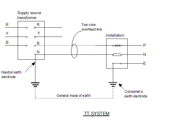
| -------TT SYSTEM------
-----===========-------------
A TT system has a direct connection to the supply source to earth and
a direct connection of the installation metalwork to earth. An example
is an overhead line supply with earth electrodes, and the mass of earth
as a return path as shown below.
Note that only single-phase systems have been shown for simplicity.
TT Network
In TT type of earthing system, consumer employs its own local earth
connection in the premises, which is independent of any earth connection
at source side.
This type of earthing is preferred in telecommunication applications,
because this system is free of any high or low frequency noise that
comes through neutral wire connected to the equipment.
The TT method is used mostly in country areas with overhead
transmission lines.
In contrast to the TN-S system there is no metallic path from the
consumer's terminals back to the sub-station transformer secondary
windings.
Because the earth path may be of high resistance, a residual current
circuit-breaker (R.C.C.B.) is often fitted so that if a fault current
flows in the earth path then a trip disconnects the phase supply.
For protection against indirect contact in domestic premises, every
socket outlet requires an RCCB with a maximum rated current of 30mA.
-----------=======--------
– About “
TT
” :
Also, it’s better to add :
– As we can use many independent
Earthing
points at consumers side only, this system is approximately used all
around the world in LV
Distribution Networks to supply Housings and buildings.
|
--------===============-----------
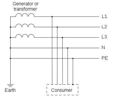
In TN type of earthing system, one of the points of the
source side (Generator or Transformer) is connected to earth. This point
is usually the star point in a three phase system. The body of the
connected electrical device is connected to earth via this earth point
on the source side. See fig. below which depicts this:
|
----------===========--------------
|
TN-S SYSTEM:
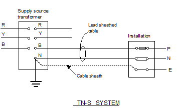
A TN-S system has the supply source directly connected
to earth, the installation metalwork connected to the neutral of the
supply source via the lead sheath of the supply cable, and the neutral
and protective conductors throughout the whole system performing
separate functions.
The resistance around the loop P-B-N-E should be no more than 0.8 ohms.
---------------============-------------
The TN-S system of wiring uses the incoming cable
sheath as the earth return path and the phase and neutral have separate
conductors. The neutral is then connected to earth back at the
transformer sub-station.
Remember in TN-S, the T stands for earth (terre), N for neutral and S
denotes that the protective (earth) and neutral conductors are separate.
|
--------=========---------
TN-C: In this, there is a combined conductor called PEN (Protective
Earth-Neutral) which is connected to earth at the source.
– About “
TN-C
” :
The following remark should be also mentioned :
– If the supply of a load is “ 3Ph + N ” and we will use only “ 1 cable
of PEN ” between the network and that load, the connection of PEN should
be done as follow “ the PEN cable should be firstly connected to the
earth point at Load, then to the neutral point ”.
|
--------==========---------
| TN-C-S SYSTEM:
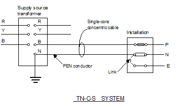
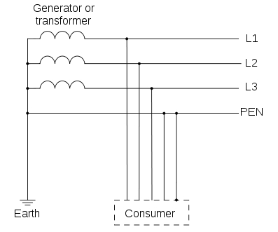
A TN-C-S system is as the TN-S but the supply cable sheath is also
the neutral, i.e. it forms a combined earth/neutral conductor known as a
PEN (protective earthed neutral) conductor.
The installation earth and neutral are separate conductors.
This system is also known as PME (protective multiple earthing).
The resistance around the P-B-N-N loop should be less than 0.35 ohms.
--------------=============------------
TN-C-S: In this type of earthing, part of the system uses a combined PEN
conductor for earthing, whereas for remaining part of the system uses
separate conductor for PE and N.
Usually, the combined PEN conductor is used near the source of the
system.
------------========------------
The TN-C-S system has only two conductors in the incoming cable, one
phase and the other neutral. The earth is linked to the neutral at the
consumer unit. The neutral therefore is really a combined earth/neutral
conductor hence the name PME(Protective Multiple Earthing).
------------==============-------
– About “
TN-C-S
” :
It’s mentioned that “ Usually, the combined PEN conductor is used near
the source of the system ”, but it’s better to say :
1- For the big networks where the installed power is big or too big, we
use TN-C
at the 1st and maybe also at the 2nd levels of the network, then we use
TN-S.
2- By this way we can decrease the installation’s costs for these 2
levels.
3- We can’t never ever use firstly “
TN-S
” then “ TN-C
”.
|
---------------================---------------
Country Specific Earthing Standards thanks to or copy this trackback: http://engineering.electrical-equipment.org/iec-standard/types-of-earthing-as-per-iec-standards.html/trackback
from your own site.
| UK |
– Uses Protective Multiple Earthing (PME) –
which is a form of TN-C-S type of earthing |
| Australia / New Zealand |
– Also uses TN-C-S type of earthing know as
Multiple Earth Neutral (MEN) system |
| USA / Canada |
Uses TN-C for the feed from Transformer but
uses TN-C-S within the structure at customer premises |
| France / Japan / Denmark |
Uses TT type of earthing and customer must
make its own arrangement for its own earthing connection |
-----------===========------------
Points
to consider in BS 7671 regulations:
Earth
electrodes:
BS 7671 lists a wide range of earth electrodes
recognised by wiring regulations, including earth rods, earth plates and
underground structural metalwork.
The single most importance deciding factor in
which type of electrode to use is resistance capacity of the soil in the
ground.
Ideally it should virgin, undisturbed ground, and the effects
of soil drying, freezing, and the potential for corrosion, should also be
considered, with tests carried out in the worst weather conditions.
Sizing of Circuit Protective Conductors
Several factors must be considered when working out the required size of
circuit protective conductor. A minimum cross–sectional area of 2.5mm2
copper is necessary for any separate circuit protective conductor, meaning
one which is not part of a cable or created by/contained inside a wiring
enclosure.
Earthing Conductors:
Earthing conductors defined by BS 7671 as a protective conductor connecting
the main earthing terminal of an installation to an earth electrode must be
sized appropriately, especially if partially buried. They must be made from
suitable material and protected against corrosion and mechanical damage. The
appropriate size is determined in the same way as for a circuit protective
conductor, except for with buried earthing conductors, in which case check
BS 7671 for further guidelines. In addition, earthing conductors for a TN–C–S
supply should not be smaller than the main bonding conductors.
Special Locations:
These are locations where extra precautions need to be taken. For
example PMEs cannot be used for caravans or boats as the combined neutral
and protective conductor is not allowed to be connected electrically to any
metalwork in them, whilst a TT system is recommended for hazardous areas
such as petrol stations, and should be accompanied by the supply of a
separate electrode and circuit breaker such as an RCD, in order to ensure
that the earthing in the petrol filling area and the PMP earth of the
distribution network are separated.
|
| |
--------------------------------=======================------------------------
|